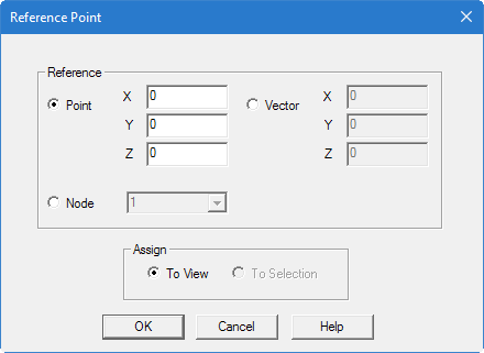
Reference Point dialog
Used to specify a direction vector for the members from which the program calculates the beta angle. The direction vector is defined with respect to the local coordinates of the member by means of a reference point.
Opens when the Beam Specifications > Beam Reference Point tool is selected from the Specifications group on the Specification ribbon tab.
Refer to Rotation by Reference section for additional information on this feature.
| Setting | Description |
|---|---|
| Point | Provide the global coordinates of the point towards which the minor axis (local y axis) of the member should be directed. The point should not lie on the longitudinal axis (local x axis) of the member. |
| Vector | A vector can be assigned with respect to the local coordinate system of the
member. The local Y axis for the member is going to oriented along this
vector. This vector does not need to be any point on the model. This can be used to orient a member without the need to calculate a beta angle. For example, vector values of X = 0, Y = 2, and Z = 1 will create a vector at a slope of 1:2 from the member's axis. The resulting beta angle = tan-1(1/2) = 26.5651°. Note: The Member Query dialog
Geometry tab will report the actual beta
angle used.
|
| Node | An existing node in the structure can be set as the reference point for one or more members. This is the alternative to defining the coordinates of the reference point. When this button is turned on, the list of all nodes in the structure will appear in the drop-down list. Select the desired node number. |
| Assign | Select the scope of members which the geometric
constant is to be assigned.
|