Home

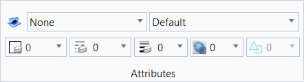
Attributes
|
Setting |
Description |
|
Used to lock the active element template when placing an element. When on, the icon is displayed with highlighting. |
|
|
Opens the Element Templates drop-down to set the active element template, and to manage element templates using the Elements Templates dialog. |
|
|
Opens the Level drop-down to set the Active Level and the Active Level Filter, to manage levels and filters, to set the display of levels and apply filters, and to recall existing level filters. |
|
| Color |
Opens the Active Color drop-down to set the active color, and change the colors of selected elements. |
|
Opens the line style drop-down to set the active line style to the line style that is chosen. |
|
|
Opens the line weight drop-down to set the active line weight and change the line weights of selected elements. |
|
|
Opens the transparency drop-down to set the active element transparency. |
|
|
Opens the priority drop-down to sets the active element priority (2D models only), which determines how an element is displayed relative to other elements. |
|
|
Opens the element class drop-down to set the active class of element on placement. |


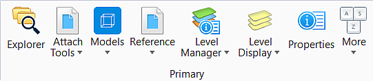
Primary
|
Setting |
Description |
|
Manage project data using the Explorer dialog. |
|
|
|
|
Models |
Displays the Models dialog, which allows you to create a new model, copy a model, edit model properties, delete and import models, create a sheet boundary, and list any filters. |
|
Turn levels on and off using the Level Display dialog. |
|
|
Turn levels on and off using the Level Display dialog. |
|
|
Review or modify information about an element(s), such as its type, attributes, and geometry. |
|
|


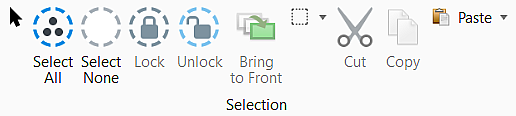
Selection
|
Setting |
Description |
|
Element Selection |
Select and deselect elements on a per element basis, by defining an area, or by drawing a line that intersects them. |
|
Select All |
Select all elements in the design. |
|
Select None |
Deselect all elements in the design. |
|
Fence Tools |
|


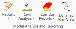
Model Analysis and Reporting
|
Setting |
Description |
|
Reports |
Reports
|
|
Civil Analysis |
Civil Analysis group
|
|
Corridor Reports |
The Corridor Reports group contains several
corridor reports. All reports require selection of a corridor to generate a
report in the Civil Report Browser. The default reports (as provided in the
installation package) are described below, however, you may select any one of
several different reports as the default.
|
Dynamic Plan View |
The tool allows you to automatically scale and rotate the view. |


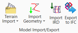
Model Import/Export
|
Setting |
Description |
|
The Import Terrain tab contains tools to create a terrain model from graphical elements, ASCII files, point clouds, LandXML, and importing from various Bentley Civil products. Tools are also supported to merge together two or more models, and to clip models. |
|
|
The Import Geometry tab contains tools for importing and exporting to / from native products (InRoads, GEOPAK and MX). It also has tools to create a "civilized" element from generic MicroStation elements. |
|
|
Import (SELECTseries 2) and prior versions of corridors contained in Roadway Designer (IRD) files. |
|
|
Finds all mesh elements with a civil feature in the 3D model and then exports them to the IFC open source format. |


