Import IRD
 Imports (SELECTseries 2) and
prior versions of corridors contained in Roadway Designer (IRD) files.
Imports (SELECTseries 2) and
prior versions of corridors contained in Roadway Designer (IRD) files.
You can access this tool from the following:

The Import IRD tool imports (SELECTseries 2) and prior versions of corridors contained in Roadway Designer (IRD) files.
The following topics are in this section: (link to details below)
- Recommendations and Limitations
- Point control target comparisons
- End condition target comparisons
- Post SS2 IRD import to SS3 required manual procedures
- Workflow: To Import an IRD
Recommendations and Limitations
- Only one corridor at a time can be imported.
- The horizontal and vertical geometry for the corridor's baseline must already exist in the design file or an attached reference file. Additionally, the 3D model that contains the 3D linear element formed by the horizontal and profile geometry must exist. If these conditions are not met, the corridor cannot be imported.
- The imported corridor will always target the active terrain model, which must already exist in the design file or an attached reference file. If no terrain model is active, the corridor may still be imported, but end conditions will not be imported. (Same result as creating a corridor with no active terrain model).
- If the first template drop in a corridor is a transition. It will not be imported.
- In order for a secondary alignment control to be imported, the horizontal alignment the secondary alignment control depends on must exist in the design file or an attached reference file. If a secondary alignment control dependency is missing, it will be reported, and the corridor may still be imported, but without that secondary alignment control.
- In order for a point control to be imported, all dependencies of that point control must exist in the design file or an attached reference file. If a point control dependency is missing, it will be reported, and the corridor may still be imported, but without that point control. For example, if a point control is a corridor feature point control, the corridor and the corridor feature must already exist. If they do not, the point control will not be imported.
- Target aliasing. In order for a target to be imported, at least one dependency for that target must exist in the design file or an attached reference file. If a dependency is not found, it will not be added to the alias list for that target. If none of a target's dependencies are found, that target will not be added to the list of targets. All missing target aliasing dependencies will be reported and a corridor may be imported with missing target alias dependencies, but without targets that are missing all dependencies.
- All dependencies will be matched by name with civil objects in the design file and/or attached reference files. For example if a point control depends on the corridor "Corridor 2" and feature "LEP", a corridor with the name "Corridor 2" must exist in the design file or an attached reference file and "Corridor 2" must contain a feature named "LEP".
- In order to match secondary alignment dependencies by name, the .alg file that contains the secondary alignment geometry must exist in the same file directory as the .ird file. This is because the .ird file does not contain a name for the secondary alignment dependency and the .alg file must be searched to get the name.
Point Control and Target Comparisons


SS2 to SS3 Comparisons
- SS2 "Alignment" = SS3 "Linear Geometry" (Name Change)
- SS2 Feature = SS3 NOT SUPPORTED (Terrain Feature Targeting)
- SS2 "Style" = SS3 "Feature Definition" (Name Change)
- SS2 "Corridor Point" = SS3 "Corridor Feature" (Name Change)
- SS2 "Elevation and Grade" = SS3 "Elevation and Grade" (No Change)
- SS2 "Elevation Difference" = SS3 "Elevation Difference" (No Change)
End Conditions Comparisons


SS2 to SS3 Comparisons
- SS2 "Surface" = SS3 "Terrain Model" (Name Change)
- SS2 "Elevation" SS3 "Elevation" (No Change)
- SS2 Feature XY = SS3 NOT SUPPORTED (Terrain Feature Targeting)
- SS2 Feature Elevation = SS3 NOT SUPPORTED (Terrain Feature Targeting)
- SS2 Feature XYZ = SS3 NOT SUPPORTED (Terrain Feature Targeting)
- SS2 "Alignment XY" = SS3 "Linear Horizontal" (Name Change)
- SS2 "Alignment Elevation" = SS3 "Linear Vertical" (Name Change)
- SS2 "Alignment XYZ" = SS3 "Linear Both" (Name Change)
- SS2 "Style XY" = SS3 "Feature Definition Horizontal" (Name Change)
- SS2 "Style Elevation" = SS3 "Feature Definition Vertical" (Name Change)
- SS2 "Style XYZ" = SS3 "Feature Definition Both" (Name Change)
Post SS2 IRD Import to SS3 Required Manual Procedures
- When targeting a SS2 Style SS3 Feature Definition via Point Control, the Linear Feature assigned as a Point Control must be Manually added as a Corridor Reference to the Corridor to be modified.
- If a Point Control targets an alignment (SS3 Linear Geometry) where the template drop and the alignment start at the exact same station location, it is likely, in SS3, the targeted alignment and optional profile will need to be extended by a tiny distance to start before the template drop for the target to be found. This is because of the conversion process and double precision calculations. Typically extending the alignment 0.001' will suffice. Although it will still appear correct in your drawing, double precision math in the 16th decimal place may introduce an inequality where the alignment according to the computer is not seen by the template drop at the exact beginning or ending until this alignment is extended slightly. It merely boils down to a precision issue. Typically if there is a miss of the targeted alignment, you are going to see a "zinger" in the 3D Model.

Template Point Style Targets

In SS2 , a template point can target a Style Constraint sometimes also refferred to as a Drafting Standard.
In SS3, the same ability exists, however the new name is now as shown
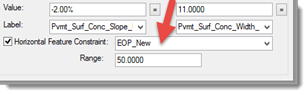
Notice in SS3, only a Horizontal target is now supported in this method.
End Condition Targets
- If an End Condition (E/C) targets an alignment, the alignment must be added to the Corridor as a reference.
- If an End Condition (E/C) targets an alignment Linear Vertical or Linear Both, the target must be defined in the Target Aliasing dialog for the Corridor as shown in an example.
- Similar to Point Controls
explained above, when targeting a Feature Definition in SS3 via an End
Condition horizontally, vertically, or both, the Linear Feature must be
Manually added as a Corridor Reference to the Corridor to be modified.
Additionally, as in the previous step 1, if an End Condition (E/C) targets a Feature Definition Vertical or Both, the target must be defined in the Target Aliasing dialog for the Corridor to find the vertical profile of the linear feature.


Superelevation
Before importing a Corridor that contains superelevation point controls, make sure to set the active MicroStation symbology accordingly to assure the superelevation sections are drawn to the correct level.