Analyze Trace Slope
 Used to dynamically trace a path on a terrain model or mesh surface.
You can access this tool from the following:

Use the Analyze Trace Slope tool to dynamically trace a path on a terrain model or mesh surface. For example, consider the path of a drop of water down a selected terrain model (or mesh surface) or up the surface to the water source. Inputs include a data point for the origin of the path.
Two Trace Methods are supported: Maximum Slope Trace and Constant Slope Trace.
When the Maximum Slope Trace Method is used with the Down option, the indicated path follows the steepest descent from the point through the terrain model or mesh terminating at a low point or the edge of the terrain model or mesh. When used with the Up option, the indicated path follows the steepest ascent from the point through the terrain model or mesh terminating at a high point or the edge of the terrain model or mesh.
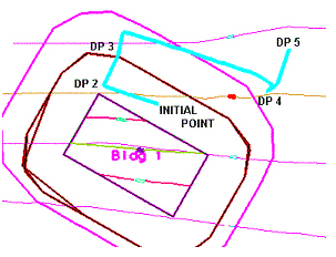
When the Constant Slope Trace Method is used, more input information is required: Slope (in terms of percent) and Distance (in terms of master units). Let’s use a slope of 5% and Distance of 500 master units. The initial data point is placed on the screen and as the cursor is moved, various solutions are displayed. Each possible solution is comprised of a line string 500 mast units long and whose slope is based on actual slope of the terrain model. Therefore, the line string meanders along a path of the specified slope until it is 500 master units long (or less if there is no solution). When DP2 is placed on the screen, the first line string which was dynamically displayed at the time of the data point is now fixed. Using DP 2 as the initial endpoint, new solutions are dynamically displayed. Note the solution between DP 3 and DP 4 has almost a 90 degree turn in it, based on the terrain of the model apartment. There is also a small turn at the end of this segment near DP 4. Note that you only datapoint to define the origin point, while the software determines the rest of the path.
One option in the (down) trace slope is the consideration of Minimum Depth. Terrain models have numerous low points, however, many of these areas are simply small indentations or dips in the model, where water would flow through to a nearby lower point. To utilize this option, set the value to a depth, in master units (feet or meters). Bentley Civil determines each low point, then determines if water placed at the specified depth overflows the indentation and flows into adjacent triangles. If it does not flow into adjacent triangles, it is utilized as a low point in the tracing procedure. If it does flow into adjacent triangles, points on the adjacent triangles are given the depth test until a point is found where the depth test does not overflow. This point is then utilized as a low point. When set to zero, the Minimum Depth is not utilized.
Workflow
1. Start the tool.
2. Select terrain model.
3. Follow the prompt in the lower corner of the screen: Alt Toggles Up Stream / Down Stream, Shift to change to Constant Slope. Alternately, set the options in the dialog.
4. Data point to display the trace path.
5. Data point to persist the transient graphics as a ruled element. Note additional data points for another trace slope may be initiated using the previous dialog settings.

|
Settings |
Description |
|
Trace Method |
Maximum Slope Trace - moves along the surface of the model or object at the specified slope. Constant Slope Trace - finds an area at 1 elevation. |
|
Slope |
Select to specify the slope. If not selected, the elevation of the model or object is used. |
|
Length |
Each trace is drawn at a maximum distance (in master units). The trace is not linear, but follows the specified slope of the model or object. |
|
Minimum Depth |
minimum low point. A value of 0.0 indicates the minimum low point depth will not be utilized. |
|
Trace Slope Direction |
Up: displays an arrow indicating direction of flow upstream from a selected point. Down: displays an arrow indicating direction of flow downstream from a given point. |
Feature
Refer to Feature Definitions for more information.