MicroStation CONNECT Edition Help

Properties Dialog

Used to review or modify the properties of an element(s), such as its geometry.

You can access this dialog from the following:

  • Ribbon: Drawing > Home > Primary > Properties
  • Ribbon: Modeling > Home > Primary > Properties
  • Ribbon: Visualization > Home > Primary > Properties
  • Ribbon: Admin > Home > Primary > Properties
  • Ribbon: File > Properties
  • Toolbox: Primary Tools
  • Reset pop-up menu: Properties.
  • Default Function key menu: <Ctrl+F12>

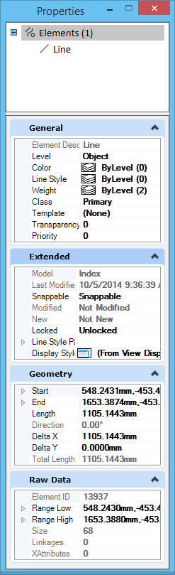
The selected element(s) is listed in the top pane. The tabs that appear in the bottom pane vary, depending on the type of element you select. Information displayed on each of these tabs pertains to the element whose list entry is selected in the top pane.

Many non-modal dialogs now provide unified selection, that is, the selection is synchronized with each other. For example, if you select a design model in the Explorer dialog, the same design model will be selected in Models dialog and its properties will be shown in Properties and Details dialogs. Similarly, if you select a model in the Models dialog, the same model will be selected in the Explorer dialog File tab (but it will not expand automatically) and again the properties will be shown in Properties and Details dialogs. Same is applicable to elements and other objects. There is also support for sub-selection. For example, if you select a Smart Solid element type in Explorer dialog File tab, and then select a particular smart solid element from the Properties dialog's selection tree, the Explorer will indicate that selection in the tree by a small arrow. If you have Details dialog open, the row in Details dialog will be automatically selected and vice versa. The same will happen in the view window as well.

The Properties dialog shows properties of any selection and is integrated with unified selection. The selection tree shows details such as associated elements, named groups, items and other data of the element as child nodes. It is also integrated with Tables (shows rows, columns, cells, etc.), parametric elements (you can expand and edit constraints and features), and so on.

The Properties dialog can be used to edit properties of data that have write permissions. This can include files, items, or elements.

Not all the settings listed below display each time an element is selected with the Properties tool. The table below displays settings on each pane in alphabetical order rather than in the order of their appearance in the dialog.

You can dock the Properties dialog to the left or right edge of the application window.

You can customize Properties dialog from the Explorer Settings.

Key-in: DIALOG PROPERTIES < OPEN | CLOSE | TOGGLE >

Note: If an element has associations, they are listed and grouped under association types, in the top pane of the dialog.

Note: If the field and its setting appear in gray text, the value is read-only and cannot be modified.

Note: If a level appears in gray text on the Model or File tab, its effective level display is off and the Follow Active View check box in the Level Display Settings dialog is off.

SettingDescription
General Displays general properties of the selected element, active model, or open DGN file.
Geometry Displays geometric properties of the selected element.
  • Affinity
  • Angle
  • Area — Determines whether a closed element is a solid or a hole .
  • Active Z depth
  • Aspect Ratio
  • Axis Ratio
  • Back Crop
  • Back Depth
  • Background Color
  • Bottom Crop
  • Bottom Height
  • Boundary Data
  • Boundary Edge Count
  • Camera Position
  • Center
  • Center 1
  • Center 2
  • Clip Origin
  • Clip Width
  • Closed
  • Control Net
  • Control Point Data
  • Control Point Data > Physically Closed
  • Control Point Data > Row Count
  • Control Point Data > Column Count
  • Control Point Data > Row Index
  • Control Point Data > Column Index
  • Control Point Data > Control Point Count
  • Control Point Data > Row Size
  • Control Point Data > Column Size
  • Control Point Data > Control Points
  • Control Point Data > Control Points > Point
  • Control Point Data > Control Points > Weight
  • Control Point Data > Weights
  • Control Point Data > Weights > Point
  • Control Point Data > Weights > Weight
  • Control Polygon
  • Count
  • Delta X
  • Delta Y
  • Delta Z
  • Dimension
  • Direction
  • Directional Vectors
  • DPI
  • Edge Count
  • Elevation
  • Elevation Angle
  • End
  • End Angle
  • End Data Point
  • End Data Point > Point
  • End Data Point > Tangent Method
  • End Data Point > Tangent Source
  • End Data Point > Tangent
  • End Point
  • Extents
  • Face Count
  • Face Data
  • Fit Point Data
  • Fit Point Data > Physically Closed
  • Fit Point Data > Fit Point Count
  • Fit Point Data > Fit Points
  • Front Crop
  • Front Depth
  • Geocoding
  • GeoPriority
  • Hidden Edge Count
  • Interior Edge Count
  • Knot Data
  • Knot Data > Uniform
  • Knot Data > Knot Count
  • Knot Data > Knots
  • Knot Data > Knot, Multiplicity > Value
  • Knot Data > Knot, Multiplicity > Multiplicity
  • Left Crop
  • Length
  • Normal
  • Number of Pixels
  • Order
  • Orientation
  • Origin
  • Perimeter
  • Periodic
  • Pixel Size
  • Planar
  • Planar Distance
  • Point Cloud > Tolerance
  • Point Cloud > Project to Cut Plane
  • Preserve Up
  • Primary Axis
  • Primary Vector
  • Radius 1
  • Radius 2
  • Rational
  • Right Crop
  • Rotation
  • Rotation X
  • Rotation Y
  • Rotation Z
  • Scale
  • Scale X
  • Scale Y
  • Scale Z
  • Secondary Axis
  • Secondary Vector
  • Segments
  • Start
  • Start Angle
  • Start Data Point
  • Start Data Point > Point
  • Start Data Point > Tangent Method
  • Start Data Point > Tangent Source
  • Start Data Point > Tangent
  • Start Point
  • Surface Area
  • Sweep Angle
  • Top Height
  • Total Elevation
  • Total Length
  • Top Crop
  • U Data
  • User Origin
  • V Data
  • View Index
  • Vertex Count
  • Vertex Data
  • Volume
Material Displays material properties of the selected element.

  • Face Attachments
  • Assigned Materials
  • Attached Material
Information Displays information about the selected terrain model.
  • Range High
  • Range Low
  • Number of Points
  • Number of Point Features
  • Number of Islands
  • Number of Holes
  • Number of Voids
  • Number of Features
  • Number of Contours
  • Number of Breaklines
  • Number of Triangles
  • Name
Edge Method Displays edge method properties of the terrain model.
  • Edge Method
  • Length
Calculated Features Display Displays calculated features properties of the terrain model.
  • Contours
  • Triangles
  • Triangle Vertices
  • Flow Arrows
  • Low Points
  • High Points
Source Features Display Displays source features properties of the terrain model.
  • Breakline
  • Boundary
  • Spot
Extended Displays extended properties of the selected element.
  • End Cap
  • Joints
  • Last Modified
  • Line Style Parameters
  • Line Style Parameters > Scale
  • Line Style Parameters > Width Mode
  • Line Style Parameters > Start Width
  • Line Style Parameters > End Width
  • Line Style Parameters > Constant Width
  • Line Style Parameters > True Width
  • Line Style Parameters > Shift Mode
  • Line Style Parameters > Shift
  • Line Style Parameters > Fraction Phase
  • Line Style Parameters > Corner Mode
  • Locked
  • Model
  • Modified
  • New
  • Profile Count
  • Profiles
  • Snappable
  • Solid
  • Start Cap
  • Thickness — Gives thickness to planar elements. If the value is positive, the thickness is applied in the positive Z (global) direction and if it is negative the thickness is applied in the negative Z direction. By default, the thickness value is zero. The native element type remains same even after applying the thickness. The thickness property can be used to visualize a planar element in a view window other than the one in which it was drawn, by giving a non-zero thickness value.
  • View Dependent
Clip Volume Displays the clip volume settings of the selected callout.
  • Angle
  • Back Depth
  • Back Crop
  • Bottom Crop
  • Bottom Height
  • Clip points
  • Elevation
  • Front Crop
  • Front Depth
  • Height
  • Left crop
  • Preserve Up
  • Right Crop
  • Top Crop
  • Toggle Direction
  • Top Height
  • Width
Annotation Displays the annotation settings of the selected callout.
  • End Margin
  • Is Annotation
  • Points
  • Start Margin
  • Style
Raw Data Displays raw data properties of the selected element.
  • Element ID
  • File Position
  • Is Range Dynamic
  • Is Range Low
  • Linkages
  • Range High
  • Size
  • XAttributes
Reference Displays reference file settings of the selected terrain model.
  • Override Symbology — When set to Yes, then the terrain model can be displayed differently when referenced without affecting how it is displayed in the original DGN file.
Clip Volume Settings Displays clip volume settings of the saved view.
  • Back Display
  • Backward Display Style
  • Back Locate
  • Back Snap
  • Cut Display
  • Cut Display Style
  • Cut Locate
  • Cut Snap
  • Forward Display
  • Forward display Style
  • Forward Locate
  • Forward Snap
  • Outside Display
  • Outside Snap
  • Outside Locate
  • Outside Display Style
Presentation Displays the presentation settings of the saved view.
  • ACS Triad
  • Background
  • Background Display
  • Basic Display Style
  • Camera
  • Clip Back
  • Clip Front
  • Clip Volume
  • Constructions
  • Data Fields
  • Default Lighting
  • Dimensions
  • Displayset
  • Fast Cells
  • Fast Curves
  • Fill
  • Grid
  • Level Overrides
  • Line Styles
  • Line Weight
  • Markers
  • Pattern/Bump Maps
  • Patterns
  • Tags
  • Text
  • Text Nodes
  • Transparency
Formatting Displays text format-specific properties of the selected element.
Contents Displays text-specific properties of the selected element.
  • Text String
  • Text Style
  • Vertical
Symbol Properties Displays symbol-specific properties of the selected element.
  • Annotation Scale
  • Color
  • Flip Direction
  • Level
  • Line Style
  • Origin
  • Ref #
  • Sheet #
  • Subtitle
  • Title
  • Type
  • Use Annotation Scale
  • Weight
Image Displays image-specific properties of the selected element.
  • Color Mode
  • Compression
  • Description
  • File Size
  • Format
  • Logical Name
  • Read-Only
Color Displays color-specific properties of the selected element.
  • Brightness
  • Contrast
  • Invert
  • Tint
  • Transparency
Display Print Displays printing and display properties associated with the selected element.
  • Clip
  • Display Gamma
  • Layers
  • Plane
  • Print
  • Print Gamma
  • Raster Rotation
  • Views
Pattern Parameters

Displays associative pattern properties of the selected element.

  • Pattern Definition
  • Pattern Cell
  • Is Annotation
  • Scale
  • Pattern Angle
  • Pattern Origin
Groups Displays grouping properties associated with the selected element.
  • Graphic Group
Attachments Displays the attachment properties associated with the selected element.
  • Angle
  • Description
  • Display
  • Display Raster Refs
  • File Name
  • Locate
  • Logical Name
  • Model
  • Offset
  • Orientation
  • Scale
  • Scale Line Styles
  • Snap
  • Transparency
  • Use Lights
Placemark Properties Displays the placemark properties associated with the selected placemark.
  • Datum
  • GCS Name
  • Input Easting
  • Input Elevation — The Cartesian coordinate system elevation used by the placemark to provide a mapping from Cartesian coordinates to WGS84 coordinates.
  • Input Latitude
  • Input Longitude
  • Input Northing
  • Number Readings
  • Placemark Name
  • Reading Time
  • Reference File
  • Reference GCS
  • Reference Model
  • Source
  • WGS84 Elevation — Used by the placemark to provide a mapping back to Cartesian coordinates from WGS84 coordinates.
  • WGS84 Latitude
  • WGS84 Longitude
Working Units Displays the working units properties of the selected model.
  • Accuracy
  • Format
  • Master Unit
  • Master Unit Label
  • Sub Unit
  • Sub Unit Label
Cell Displays cell properties of the selected model.
Sheet Displays the properties of the selected sheet model.
  • Display Boundary
  • Sheet Number
  • Sequence Number
  • Border Attachment
  • Sheet Size
  • Width
  • Height
  • Origin
  • Rotation
  • Sheet Index
Drawing Properties Displays the properties of the selected drawing model.
  • Reference - Details of the reference attached in the drawing model such as the logical name, file name, and description.
  • View Type - Type of saved view.
  • View Name - Name of the saved view.
  • Discipline - Discipline of the drawing.
  • Purpose - Purpose of the saved view.
Breaks Displays the property for applying breaks to a table.
  • Break Type
Text Styles Displays the properties of text styles of text in a table.