Create Model Dialog
| Setting | Description |
|---|---|
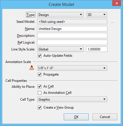
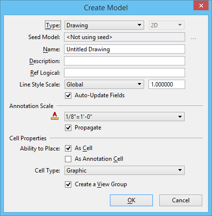
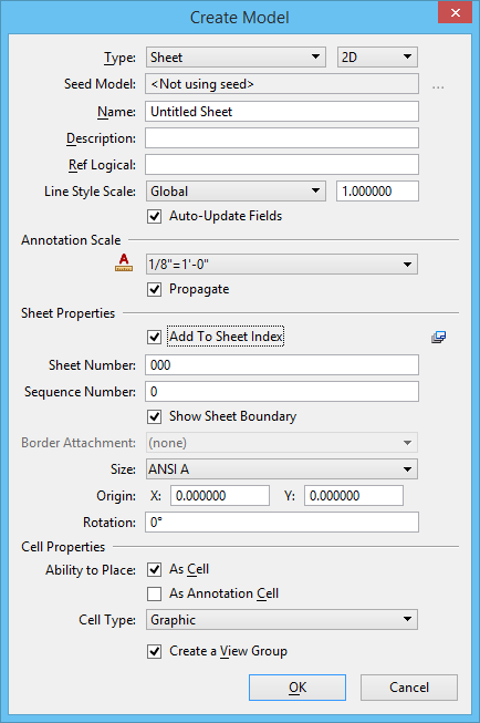
| Type | Sets the type of model created.
|
| Seed Model | Sets the seed model. Clicking the Change Seed Model icon next to the Seed Model field opens the Select File Containing Seed Model dialog. After selecting a file, the Select Models dialog opens, which lets you select a seed model. |
| Name | Text field into which you can enter a name for the model. |
| Description | Text field into which you can add a description of the model. |
| Ref Logical | Sets the logical name for the model. The logical name identifies the model when it is attached to another model as a reference. |
| Line Style Scale | Lets you choose the scale for line styles (Global,
Annotation Scale, or Compound Scale):
|
| Auto-Update Fields | If on, fields are automatically updated when a file is opened. The rules governing how fields are updated are controlled by the MS_AUTO_UPDATE_FIELDS configuration variable. |
| Annotation Scale |
Choosing a value from this list sets the scale factor for
text elements, dimensions, text nodes, notes, detailing symbols, annotation
cells, hatches, patterns, tags, and line styles placed in the model.
The default scales are stored in the Scales.def file, which is defined at the System Configuration Level and is located in the ..\Default\Data\ folder of MicroStation's program directory. To define custom scales, move or copy the Scales.def file to any other Configuration Level, define the Configuration Variable MS_CUSTOMSCALEDEF to point to the new path and the file, and add custom scales to the file. For example, move the Scales.def to the WorkSpace's ..\Organization\Data\ folder and define the path in the MS_CUSTOMSCALEDEF configuration variable. For more information on using annotation scale, see Creating sheet models for drawing production. |
| Propagate | Propagates the model’s annotation scale. The behavior of this setting is same as the MS_ANNOTATIONSCALEPROPAGATION configuration variable. |
| Add to Sheet Index | (Sheet Model only) Adds the sheet model to the
sheet index.
Note: If some other
user already has the sheet index in edit mode, the sheet model cannot be added
to the sheet index. In such case, a message is displayed in the message center.
|
| Select a folder from Sheet Index |
(Sheet Model only) Opens the Sheet Index Folder Picker from
which you can select the folder in which the sheet model should be added.
|
| Sheet Number | (Sheet Model only) Lets you assign a sheet number to sheet models. If you add the sheet model to the sheet index, the sheet number is inherited from the Sheet Number property in the sheet index. |
| Sequence Number | (Sheet Model only) If you add the sheet model to the sheet index, the sequence number is inherited from the Sequence Number property in the sheet index. |
| Show Sheet Boundary | (Sheet Model only) If on, a gray element representing the extent of the sheet boundary appears in the new sheet model. |
| Border Attachment | (Sheet Model only) Sets the border to be attached as a reference, which comes from the seed model. |
| Size | (Sheet Models only) Sets the sheet size. Standard
sheet sizes are available from the list, or you can select Custom and input
your own size values in the Height and Weight fields.
The default sheet sizes are stored in the Sheetsizes.def file, which is defined at the System Configuration Level and is located in the ..\Default\Data\ folder of MicroStation's program directory. To define custom sheet sizes, move or copy the Sheetsizes.def file to any other Configuration Level, define the Configuration Variable MS_CUSTOMSHEETSIZEDEF to point to the new path and the file, and add custom sheet sizes to the file. For example, move the Sheetsizes.def to the WorkSpace's ..\Organization\Data\ folder and define the path in the MS_CUSTOMSHEETSIZEDEF configuration variable. |
| Origin | (Sheet Models only) Sets the origin of the sheet boundary. |
| Rotation | (Sheet Models only) Sets the rotation angle of the sheet boundary, measured in degrees counterclockwise from the x-axis (horizontal). |
| Ability to Place > As Cell | If on, it is possible to place the model as a cell. |
| Ability to Place > As Annotation Cell | (Available only if Can be placed as a cell is on)
If on, it is possible to place the model as an annotation cell. When placed as
an annotation cell, the current annotation scale is applied to the cell.
|
| Cell Type | (Available only if Can be placed as a cell is on) Sets the cell type to Graphic, Point or Parametric. |
| Create a View Group | If on, a View Group is created with the model. |

