PlantBuilder Model
Using PlantBuilder, you can create conceptual 3D models of plants based on process description, plot layout, and libraries with definitions for equipment, pipeways and structures. The process description, or process model, relates to all things involved in the operation of a plant. For example, pieces of equipment are defined in the process model. The plot layout, or plot script, contains all the physical information of the plant. The equipment that is defined in the process model is given shape and location in the plot script.
To create a plant model, the following steps must be completed in more or less the following order:
- Create a project. A project is a collection of designs that uses the same base design data. It uses a single dimensional system. Other projects may use another unit system and may use modified base design data. A project can be copied and deleted both within or outside of the software.
- Create a model. A model is a single design entity, typically a process plot or plot alternative. A project may have many models, of which only one is active at any one time. A model can be saved, copied and deleted.
- Within a model, create a process model. The base for a process model is information from a P&ID or PFD.
- Create a physical model of the plant, including equipment representations, and structures like pipeways, multilevel structures, pedestals, other obstacles, etc.
- Place nozzles on the equipment either using the AutoNozzle command or manually.
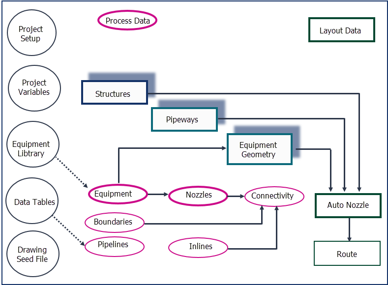
Because some elements of the
PlantWise are dependent on others, the
following conditions must be followed:
- nozzle data cannot be defined before its corresponding equipment is defined;
- equipment geometry may not be defined until equipment is defined and must be defined before nozzle geometry may be calculated;
- pipeways and equipment geometry should be defined before nozzle geometry rules can be run; and
- equipment, structure, and pipeway data are independent of any other data and may hence be defined at any time and in any order.
- define equipment (see Equipment List);
- define nozzles (see Nozzle List);
- define pipeways (see Pipeway Builder);
- define structures (see Structure Builder);
- define equipment geometry (see Equipment Editor); and,
- define nozzle placement (see Placing Nozzles).