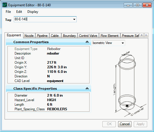
PlantWise Help

Equipment Editor

Where you can define and change any geometric aspect of a piece of equipment: location, size, or orientation.

  • If the editor is opened from a menu, it opens completely empty and you need to select a piece of equipment from the drop down list.
  • If the editor is opened using the Edit tool icon on the Plant Toolbox, it opens with the selected equipment’s data filled in.
  • Finally, if the editor is opened via the Place Equipment tool icon on the Plant Toolbox, it opens with the inferred data from the CAD graphic.

The dialog is divided into four parts: identification, placement, attributes, and commands. In addition, there are menus to control editing and display options.

Equipment Editor.

Dialog part Description
Identification The Tag identifies the selected equipment. The Type and Description for equipment are both read from the process model. Any defined piece of equipment can be selected from the drop down menu.

Each class of equipment in the Equipment Library provided by Bentley Systems has several .gif files that can be viewed in the Equipment Editor. Different views can be selected from the drop down list between the Common Properties and Class Specific Property panes.

Attaching image files to the dialog is discussed in Equipment Picture Files for Equipment Editor.

When the dialog is opened, the image file is compressed to fit into the picture region of the dialog. This reduction can reduce the quality of the picture; therefore, you can click on the image to expand it to full size. You need to resize the Equipment Editor dialog to view the full picture. Clicking on the image reduces it to the default size.

Location and Orientation If the dialog was opened through a menu for an unplaced piece of equipment, only the elevation (defaults to site grade) and the orientation (defaults to north) fields are filled in.

If the dialog was opened with the Place Equipment tool icon on the Plant Toolbox, PlantWise determines the plan view location (x- and y-coordinates) directly from the rectangle or circle selected in the CAD drawing (see Equipment Placement with CAD).

While default orientations are either north, south, east, or west, you can enter any angle (clockwise from north) for the piece of equipment.
Attributes (Properties) The parametric equipment model uses a limited set of attributes as the basis for all elemental dimensions. These attributes are equipment-specific and are specified in the Equipment Class Editor when the parametric model is defined in the Equipment Library, and is discussed in Adding Attributes to an Equipment Class.
Commands
  • Apply places the specified equipment or obstacle geometry. Once the equipment is accepted, it is moved to the Placed Equipment column in the Equipment Selection dialog. The 3D rendition of the equipment [obstacle] appears on the CAD screen properly located, oriented and dimensioned.
  • Cancel closes the dialog and discards any data entered since the last Apply.
Menus
Menu Description
File menu Allows you to Save Model, Save Model As, and Close the dialog.
Edit menu
  • Copy Equipment generates a duplicate of the current piece of equipment – including its nozzles – by prompting you for the name of the new equipment and location information.
  • Rename Equipment lets you change the name of a piece of equipment.
  • Nozzle List links you to the Nozzle List dialog for the selected equipment instance.
  • Nozzle Editor links you to the Nozzle Editor dialog for the selected equipment instance;
  • Equipment List gives access to the Equipment List dialog.
  • Elements opens the Equipment Element Browser which lets you view the geometric data of the separate components of the specified piece of equipment.
  • Equipment Class allows you to edit the equipment class variable, including adding user defined attributes for a piece of equipment (see Editing Equipment Classes) .

    Equipment Element Browser.

  • Equipment Sheet opens the Equipment Class Sheet, which groups equipment by class.
  • Geometry Rules provides quick access to the equipment geometry specification of the selected equipment. See Defining Equipment Geometry;
  • Nozzle Rules provides quick access to the equipment nozzle placement specification of the selected equipment. See Defining Nozzle Placement Rules ;
  • Vicinity Rules lets the AutoRouter user edit how a pipe would leave/enter a nozzle (see Defining Equipment Vicinity Routing Rules).
  • Proximity Checking opens the Proximity Conflicts dialog.
  • Delete lets you delete a piece of equipment.
Display menu
  • Toggle Obstacle Boxes toggles the display of the routing obstacles enclosing the selected equipment. By default, obstacle boxes are not drawn.
  • Toggle Vicinity Routes toggles the display of the vicinity routing rule path for each nozzle on the equipment.
  • Zoom To causes CAD to prompt you to select a view. When a view is selected, the currently selected component fills that view.

    You can then select other views in CAD and they also be zoomed so the component fills the view.

    Note: Some times the Zoom To affects the clipping planes. If the component does not appear in the view, turning off the front and/or back clipping plane should make the component visible.
  • Highlight changes the drawing level of the selected equipment to Highlight (drawn in magenta) so that it can be easily located.
  • UnHighlight returns the selected equipment to its normal drawing level.
  • AutoNozzle Equipment places the nozzles for the specified piece of equipment.
  • Thaw Placed Nozzles gives control of nozzle placement back to the AutoNozzle command.
  • Freeze Placed Nozzles sets the locations of placed nozzles so that the AutoNozzle command does not overwrite the placements.
  • Mass Properties opens the Mass Properties dialog for just the selected piece of equipment.
  • My Groups opens a Named Groups dialog that lists all the groups that contain the selected piece of equipment.
  • All Groups opens the All Named Groups dialog.
Any changes in the Equipment Editor must be Accepted before they takes effect.