Placing Nozzles
Nozzles can be positioned either by using rules or interactively. All nozzles are placed on a face of an element of a piece of equipment. By default, nozzles are placed outward and orthogonal to the face of the element. The nozzle placement rules are included in the equipment library and there is a rule for each piece of equipment. It is possible that the placement of a nozzle according to the rules is off the face of the element; if that occurs, the program reports the error and places the nozzle. At that point, you would manually alter the placement of the nozzle.
Input-Based Nozzle Placement
The placement and orientation of nozzles can be given as inputs in the Plot Script file as described in Nozzle Definition .
Rule-based Nozzle Placement
The Nozzle Locator allows definition of default, equipment-type-specific, parameter-controlled nozzle placement rules using the Nozzle Placement Language. This language lets you refer to the different equipment elements, to previously placed nozzles, to the type of nozzle, as well as to other locations such as pipeways or the other end of a connected pipe. For more details, see Defining Nozzle Placement Rules.
Nozzles placed using the Nozzle Placement rules, use the AutoNozzle command. To place all the nozzles in the model, use the AutoNozzle All command under the Router menu in the PlantWise window. To place nozzles for individual pieces of equipment, use the AutoNoz tool icon on the Plant Toolbox or through the Display menus in the Equipment Editor, Nozzle Editor, or Nozzle List.
If nozzles have already been placed, you will be prompted by the AutoNozzle Control dialog with the following placement options:
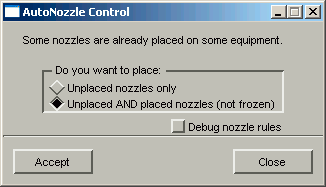
All nozzles (unplaced, placed, and frozen) are used in interpreting the nozzle placement rules to assign nozzles to rules and offset clauses. Placed nozzles that are not eligible for the current rule or frozen nozzles are not given new locations, rather they are used as reference for the placement of the remaining nozzles. For example, if the inlet nozzle A1 is placed and frozen, subsequent unplaced inlet nozzles A2 and A3 will be placed relative to the actual frozen nozzle position in a nozzle and offset rule combination. This approach minimizes the possibility that nozzles are placed in overlapping positions unless the placement rule allows it.
If you believe that the placement rule is not placing nozzles properly, select the Debug nozzle rules button on the AutoNozzle dialog. This will list what rule placed each nozzle in the PlantWise Command Interpreter.
Manual Nozzle Placement
For equipment with complex nozzle placement, it can be preferable to manually locate nozzles.
To position a nozzle manually:
- Select Edit tool icon in the Plant Toolbox and click on the nozzle to be relocated in the MicroStation window. (Or select the Edit in the Nozzle List.) This opens the Nozzle Editor with the current data for the selected nozzle.
- Change the element on which the nozzle is mounted using the Element selection box.
- Change the face of the element on which the nozzle should be mounted using the Face selection box.
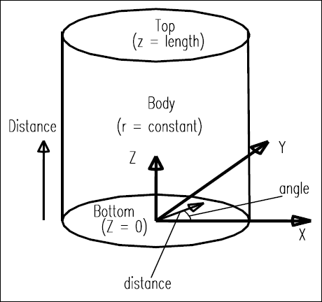
- If the element is a cylindrical type element (cylinder or elliptical head), locations are given in cylindrical coordinates. For the top or bottom faces the distance parameter is the distance from the center of the face and the angle is the angle for the location to which the nozzle should be relocated. For the body of the cylinder, the distance is measured from the bottom face.
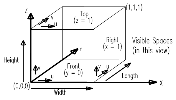
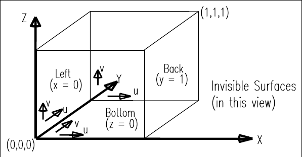
- If the element is a rectangular type element, then the location is given in local coordinates (u and v) for each face (front, back, top, bottom, left, and right) as shown below (visible surfaces and invisible surfaces).
- The nozzles are placed perpendicular to the face surface in an outward direction by default. To deviate from this direction, select the Optional Rotation check box and enter the rotation angle around the local coordinates of the element from this direction in degrees.