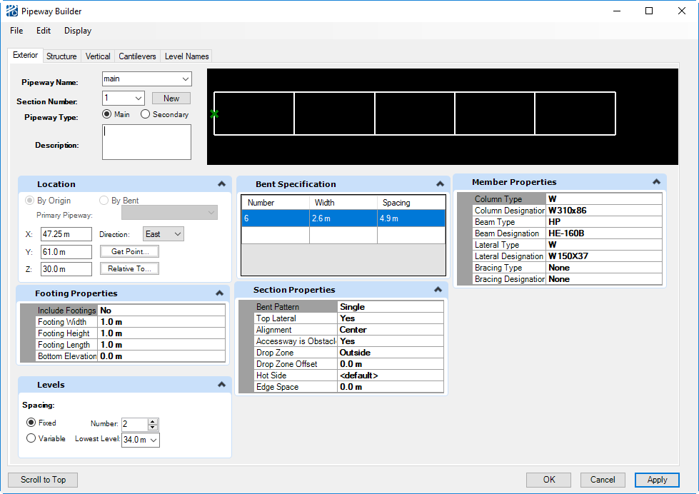
Pipeway Builder
The Pipeway Builder has a tab for each type of pipeway, Exterior, Structure, and Vertical. It also has a tab for adding Cantilevers to Exterior pipeways, and a tab for setting the Level Names.
Menus
| Setting | Description |
|---|---|
| File menu | Allows you to Save Model, Save Model As, and Close the dialog. |
| Edit menu |
|
| Display menu |
|
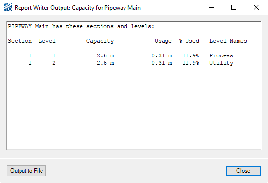
The Capacity Report
To optimize pipeway capacity design, you will need to know how much of each pipeway level is being used.
The Capacity Report lists pipeway space by section level.
The figure below shows a pipeway that is over-loaded on Levels 1 and 2 of Section 1 as well as on Level 1 of Section 2.
Pipeway Attributes
- Pipeway Name is where the you name the new pipeway. If editing an existing pipeway, you can select the desired pipeway from the Pipeways drop down list.
- Pipeway Type is where you define if the pipeway is a Main, or Secondary.
- Pipeway Location is where you define X, Y, and Z coordinates as well as the Orientation of the pipeway.
- The Description field is optional.
| Attribute | Description |
|---|---|
| Footing Properties | If set to Yes, adds a box for each column. The size of the box will be based on the dimensions specified in this property pane. |
| Levels | Levels can be specified as either a fixed offset, the
Project Setup Routing Plane Offset or Variable levels.
When the Fixed option is chosen the Number of levels and the Lowest Level elevation must be specified. For variable spacing between levels, you can select the Variable Elevations option and enter the elevations for all the approach and berthing levels. You must define elevations for all approach and berthing levels.For example, a two level pipeway in an Imperial
unit model with approach levels at 114 ft 4.0 in, 118 ft 6.0 in, and 123 ft 4.0
in and berthing levels at 116 ft and 121 ft 6.0 in would have the Variable
Elevations set to:
|
| Bent Specification | This pane is used to set the Number, Width, and Spacing of bents. If the member properties are to remain the same, the Width and Spacing can be changed within a single section by entering the new values in subsequent rows. |
| Section Properties | Section Properties apply to all bents in the section.
The properties that can be set are:
|
There are two ways to build a pipeway in PlantWise. First, by using two dimensional graphics in CAD; and second, directly in the user-interface.
Open the Pipeway Builder from menu in CAD. This dialog is used both for creating new pipeways and for editing or inquiring about existing pipeways.
Creating Main Pipeways
The first pipeway in a PlantWise model is a Main pipeway. Subsequent pipeways can also be main pipeways, or can be built off of an already existing pipeway as a secondary pipeway. .
- Enter the desired name in the Pipeway Name entry field. (The Section Number defaults to 1.)
- Select Main Pipeway in the Pipeway Type field.
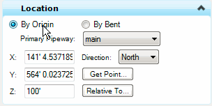
- Locate the pipeway section on the plot by entering the coordinates of the center point of the first bent into the Origin entry fields.
- Select a direction in the Orientation field.
- Enter the desired
properties of the pipeway’s section into the appropriate entry fields.
- Width is the distance between column center lines in a bent.
- Number of Bents is the number of bents in the section under definition.
- Number of Levels is the number of pipe-supporting beams in a bent.
- Lowest Level Elevation of the Main Pipeway determines the routing planes of the plot. All routing plane elevations are calculated as increments from this level. The default level distance the routing plane offset defined in the Project Setup dialog. In a multilevel section, the elevation distance between pipeway levels is twice the project specific default level distance.
-
Select the steel or concrete shapes of its Columns, Beams and Laterals from the appropriate drop down selection lists. The available steel and concrete shapes are listed in Nozzle Definition , and can be edited to include additional shapes needed. Column and Beam shapes must be given values; however, a value for Lateral is optional.
- Apply builds the pipeway section in the plant model and on the CAD screen.
- After the pipeway section is created, proceed to define additional sections, other main or secondary pipeways, or exit the Pipeway Builder by clicking Cancel.
Place Pipeway
You can also Place a pipeway with a CAD graphic in a manner similar to how obstacles are placed with this method (as described in Obstacle Placement with CAD). You can draw a rectangle in CAD and then use the Place Pipeway button on the Plant Toolbox to assign a pipeway to that graphic. The Pipeway Builder opens with the location and geometry information of the selected rectangle. You will need to provide data PlantWise could not determine from the graphic and may want to correct information that PlantWise did not correctly assume.
The origin and direction will be provided. The direction will be along the long axis of the rectangle, either North or East.
The width of the pipeway will be equal to the short axis of the rectangle assigned to the pipeway. The number of bents is equal to the length of the pipeway divided by the width (rounded up to the next integer). Bent spacing is then the length divided by the number of bents minus one.
- number of bents (N) = Length/Width (rounded up to next integer)
- bent spacing = Length/(N-1)
Creating a Secondary Pipeway
A secondary pipeway is generally connected to another pipeway. Any secondary pipeway is perpendicular to its primary pipeway. When connected to its primary pipeway, one of the columns in the first bent of a secondary pipeway is shared with a column in the connecting pipeway. After the original placement, a secondary pipeway may be relocated – dynamically or via the Pipeway Builder – to any location in the model.
To create a secondary pipeway:
- Open the Pipeway Builder dialog (if it is not open already) with the Pipeways command in the Plant menu.
- Give the secondary pipeway a Pipeway Name.
- Select Secondary Pipeway in the Pipeway Type field.
- The Pipeway Builder dialog is reconfigured to simplify locating the origin of the secondary pipeway. The new fields that appear in the dialog are the Primary Pipeway selection menu and the Origin Specification buttons allowing you to specify the origin By Origin or By Bent.
- Select the pipeway to which the secondary pipeway will be connected with the Primary Pipeway option button.
- Select either the
By Origin or the
By Bent option.
Selecting By Origin activates fields for typing in X, Y, and Z coordinates.
- The Get Point button prompts you to "Pick a point to return to D++." When a Data Point is entered in CAD in response, fills the X, Y, and Z values of the Data Point.
- The
Relative To button opens an auxiliary
dialog.
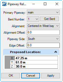
- When a Primary Pipeway and Bent Number are selected, highlights the bent in CAD and updats the Proposed Location based on the settings in this dialog.
- Clicking the Get Bent button, prompts you Pick a point to return to D++. When a Data Point is entered in CAD in response selects the bent nearest to the Data Point.
- If the point is closer to a bent in another pipeway, the Primary Pipeway field will be changed to the new pipeway.
- The Alignment choices are Centered in the bay either side of the selected bent, or Aligned with the column on either side of the selected bent.
- The Alignment Offset allows you to enter an offset from the specified alignment point.
- The Edge Offset allows for placing the pipeway the specified distance away from the edge of the Primary Pipeway.
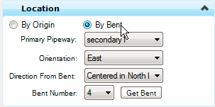
Selecting By Bent (the recommend method) changes the Origin entry to allow defining the shared column of the connecting Primary Pipeway. The data required for the By Bent option are the Bent Number and the Direction from Bent.
- Enter the Bent Number, which is the bent number counted from the origin bent of the pipeway, not the section.
- Clicking the
Get Bent button, prompts you Pick a
point to return to D++. When a Data Point is entered in CAD in response
selects the bent nearest to the Data Point.
If the point is closer to a bent in another pipeway, the Primary Pipeway field will be changed to the new pipeway.
- Select the Direction from Bent, which is the direction from the shared column in which the second column of the starting bent should be placed. The direction selection is one of two depending on the direction of the connecting Primary Pipeway. If the Primary Pipeway is laid out in the East-West direction, then the selection should be either E or W. If the Primary Pipeway is laid out in the North-South direction, then the selection should be either N or S.
- Select the Orientation of the secondary pipeway. Orientation determines the direction in which the secondary pipeway extends from the connecting Primary Pipeway and which side of it the Secondary Pipeway is connected to. Orientation is restricted depending on the direction of the connecting Primary Pipeway. If the Primary Pipeway is laid out in the East-West direction, then the Orientation selection should be either N or S. If the Primary Pipeway is laid out in the North-South direction, then the Orientation selection should be either E or W.
- Specify a Section Number (always starting with 1 for each pipeway).
- Once the origin is
selected, the construction of the secondary pipeway follows the same process as
main pipeway. (Specify
Section Number [always starting with 1],
Structural Members, and
Size.)
You are encouraged to select the lowest level elevation from the Lowest Levels drop down list to insure proper vertical spacings between perpendicular berthing levels.