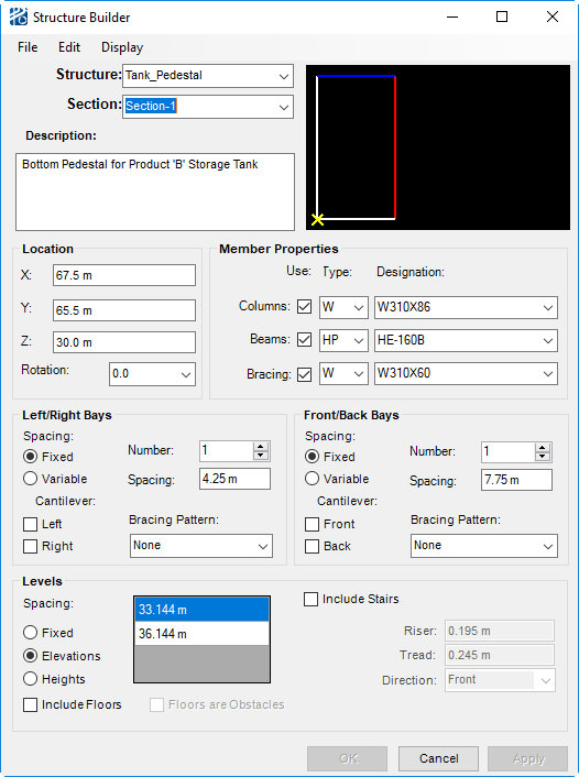
Structure Builder
The Structure Builder is used to create and edit structure sections and is opened either from the Edit Structure tool icon on the Structure Toolbox, or from the menu choice in the PlantWise dialog, or from the Edit Structure tool icon on the Structure Toolbox.
The dialog is broken into nine sections:
- Menus
- Name
- Structure Preview
- Location
- Member Properties
- Left/Right Bays geometry
- Front/Back Bay geometry
- Levels
- Command Buttons
The following sections discuss each of these parts of the Structure Builder.
Menus
There are three menus in the Structure Builder Dialog: File, Edit, and Display.
| Menu | Description |
|---|---|
| File | |
| Edit |
|
| Display |
|
Name
Even if a structure is made up of only one section, the structure and the section are individually named. This practice allows you to vary geometry within the structure while maintaining the sense of a building. The sense of building can be valuable for edits made through CAD and reporting.
In the Structure Name field, you can select an already existing structure to edit or enter the name of a new structure. To guarantee that a new structure name is accepted, it is best to either Tab out of the field, or press <Enter> while in the name filed.
In the Section Name field, you can select an already existing section to edit, or enter the name of a new section. To guarantee that a new section name is accepted, it is best to either Tab out of the field, or press <Enter> while in the name filed.
The Description field allows you to enter a longer description of the structure section.
Section Preview
So you can better visualize the structure being created, there is a preview window to the right of the Member Properties section of the Structure Builder.
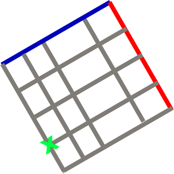
The preview window reflects, in plan view, the current
contents of the structure builder, even if the section has not been accepted.
The placement point is represented by a
 X; the Back face of the section is represented
by a
X; the Back face of the section is represented
by a
 line; and the Right face is
indicated with
line; and the Right face is
indicated with
 .
.
Location
Each structure section is independently located at the bottom of the front- and left-most column.
A section’s location is composed of X, Y, and Z coordinates as well as its counter-clockwise Rotation about the originating column. Although the values in the Rotation drop down list are increments of 90, you can enter any rotation value. As with structure and section names, pressing the <Enter> or <Tab> while in the Rotation field, ensures proper registration of the section’s rotation.
| Setting | Description |
|---|---|
| Place Structure Section | You can also place a structure with a CAD graphic in
a manner similar to how obstacles and pipeways are placed in this manner. You
can draw a rectangle in CAD and then use the
Place Structure button on the
Structure Toolbox
to assign a structure to that graphic. The Structure Builder opens
with the default member shapes and designations selected in the Member
Properties section as well as the location and geometry information of the
selected rectangle. From that rectangle,
PlantWise assumes a one bay structure
with:
You need to provide a z-ordinate (if other than grade) as well as level spacing. |
| Member Properties | In the Member Properties area of the Structure
Builder, you choose whether the section to have
Columns,
Beams, or
Bracing and what type of member be used for
each.
By selecting or un-selecting the Use check box for each member category, you define if there be columns, beams, or bracing members used in the structure section. The Type and Designation of those members are selected from their individual drop down lists. When selecting to use columns, beams, or bracing, a Type and Designation must be provided. These designations serve as defaults for the structure and can be changed at any time. Individual member type and designation can be changed be changed through the Bay Editor and the Structure Member Builder.Default beam, bracing, and column designations are set in the Structure category of the PlantWise Project Setup dialog (see Setup Variables). |
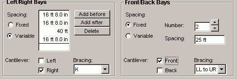
| Left/Right and Front/Back Bays | Because structure sections can be rotated, the sides
of a structure are not based on direction (north, south, east, west), rather
the sides are front, back, left, and right. Therefore, when defining bay
spacings, cantilevers, and bracing, you provide values separately for the
Left/Right and Front/Back directions.
|
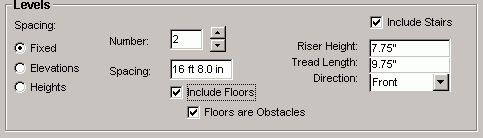
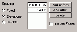
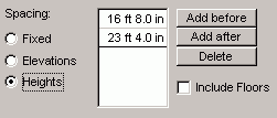
| Levels | Vertical attributes of the structure section are
defined in the
Levels section of the
Structure Builder.
The three ways to define elevation spacings: fixed, variable elevations, and variable heights.
As with variable bay spacing, you can add and remove level elevations or heights with the Add before, Add after, and Delete buttons. |
| Floors | Structure floor functionality adjusts to the your’s
need. Floors can be excluded from the section, included in the section for
reporting purposes, or included as an obstacle to routing.
Selecting the Include Floors check box includes floors in the structure section for reporting and mass property calculations. By then selecting the Floors are Obstacles check box, you further define if the floors be act as obstacles to pipe routing. Default floor settings are set in the PlantWise Project Setup dialog in the Structures section (Floors Are Obstacles By Default? and Use Floors?). Floors are
Obstacles must be checked if structure routing functionality
(structure pipeways, vertical pipeways, vertical chases, and floor
penetrations) be needed for the structure section.
Similarly, Floors are Obstacles must be checked for proper automatic placement of placeable inline components. |
| Stairs | Stairways are added to a structure by selecting the Include Stairs check box in the Levels section of the Structure Builder. When checked, the default values for Riser Height, Tread Length, and Direction becomes active for you to edit. Direction indicates at what side of the bay the bottom stair will be approached from. For example, a Front direction stairway to go up from the front of the bay to the back of the bay. |
Command Buttons
- Accept builds
the section in the model and on the CAD screen.
After accepting the section, the section data remains in the entry fields in anticipation that only a few changes are needed to build the next section of the structure. A new section is defined by providing a new Section Name and changing the data in the necessary value fields.
- You can exit the Structure Builder by clicking Close. Any data entered after last Accept is discarded.
Editing Sections
Structure sections are edited by changing attribute values in the Structure Builder dialog while the structure and section are listed in their appropriate name fields. Changes are implemented once you click Accept.
To select the section to be altered, you can:
Copying Structures and Structure Sections
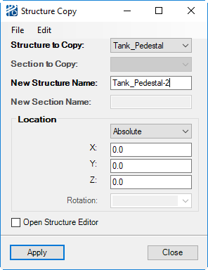
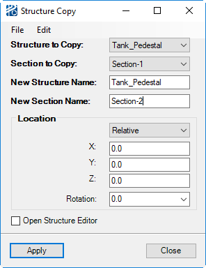
You can copy complete structures or specific structure sections that will maintain any customizations to members, bays, and bracings. Both the Copy Structure and Copy Section dialogs are opened from the Structure Builder Edit menu.
| Setting | Description |
|---|---|
| Copy Structure | Once the
PlantWise Structure Builder - Copy
Structure dialog is open, you need to provide a
New Structure Name as well as the name of
the section that will be placed or offset to locate the new structure (Location
refers to). Additional sections will be copied and moved by the same vector as
the referenced section. You can then select to provide
Location coordinates for the new structure,
or
Offset values in the X, Y, and/or Z
direction. Both placement options allow you to provide additional
Rotation for the new structure.
For the new structure to be created, you must click Accept. The Close button cancels the Copy Structure without implementing the new structure. |
| Copy Section | Copy Section is very similar to copy structure. Once
the
PlantWise Structure Builder - Copy
Section dialog is open, you must supply a
New Section Name, but the
New Structure Name is optional. Placement of
the structure can be by
Location or
Offset, and additional
Rotation can be added.
For the new section to be created, you must click on the Accept button. The Close button cancels the Copy Section without implementing the new section. |