M. To create an I shape user table section
To create a user-provided table section with an I section profile, including those with composite flanges or tapered web depth, use the following procedure.
You may want to change the input dimensions prior to creating user provided table sections. Select to do so.
This user-provided section allows you to specify a tapered I-Section with an optional composite top flange. For I sections with a bottom steel plates, you must create a prismatic wide flange section. Alternatively, you may use a tapered I section when a non-composite section is required.
-
On the
Specification ribbon tab, select the
tool in the
Beam Profiles group.

If no User Defined Table exists, you will be prompted to create one.
The User Table Manager dialog opens.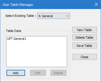
- Required:
Enter the following wide flange section parameters:
- TWW
- Thickness of web
- TFF
- Thickness of top flange
- BFF
- Width of top flange
- TFF1
- Thickness of bottom flange
- BFF1
- Width of bottom flange
- Depth at Start Node
- The overall depth of the section at the starting node.
- Depth at End Node
- The overall depth of the section at the ending node. Note: This must be less than or equal to the depth at the start node (i.e., the section depth must taper down from start to end nodes or remain constant depth).

Figure 1. I section and tapered web
The section can now be added for use in the dialog by selecting it in the User Property Table dialog.