To apply a defined wind load to your structure, use
the following procedure.
Either:
On the
Loading ribbon tab, select the
Load Items tool in the
Loading Specifications group
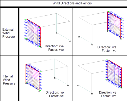
Tip: This will add the load item to
the currently selected load group selected in the program status bar.
In the
Load & Definition dialog,
select a primary load case in the
Load Cases Details list and then click
Add.
The
Add New Load Items dialog opens.
Select the
Wind Load > Wind Load tab.
Note: If you have not
previously added a wind load definition to the model, this tab is inactive.
Refer to
M. To add a wind load definition for details.
In the
Select Type drop-down list, select the wind
load definition for this load case.
Select the
Direction of the load and then type the load
Factor value.
X (External)
Y (External) - for Z Up
Z (External) - for Y Up
(default)
-X (Internal)
-Y (Internal) - for Z Up
-Z (Internal) - for Y Up
(default
The direction options are dependant upon the global orientation of the model.
The selected Direction and sign of the
Factor affect how the wind is applied (i.e.,
internal or external pressure for an enclosed
structure).
Optional: If the wind load definition is for a SNiP code, specify the
additional SNiP Parameters:
Select the configuration from the drop-down list.
Type the wind pressure coefficient.
Specify the range of values over which the load applies. Type the
along the global axis of how the wind load acts.
Depending on the arrangement of walls, you may need to
sub-divide the wind load application into multiple entries with overlapping
ranges. The program may not automatically recognize all open-ended wind panels.
Refer to
Controlling Open-Ended Panel Identification for additional details.
Tip: Alternately, you may specify
member lists or group definitions using the command input.
Optional: Check the
Open Structure option for truss, lattice, or
other open structure types.
This will apply the load only to the projected area
of the members and joints, not to the bounded area of members or surfaces.
Click
Add.
The program will
automatically calculate the joint loads for structure that lies within the
specified range. Selecting the wind load item in the
Load & Definition dialog will
highlight the loading members. The calculated surface exposure and the
tributary areas will also be displayed for closed structures.
Review the wind panels for each wind load case to ensure that the
intended areas are loaded. The panels are color coded to identify unique
tributary areas.