TR.32.12.3 Generation of Wind Loads
This command is used to generate Wind Loads using previously specified load definitions. This command should be part of a load case.
The built-in wind load generation facility can be used to calculate the wind loads based on the parameters defined in TR.31.3 Definition of Wind Load. The following general format should be used to perform the wind load generation. See G.16.3 Wind Load Generator for the two types of structures on which the load can be generated. For closed type structures, the vertical panel areas bounded by beam members only (and ground), and exposed to the wind, are used to define loaded areas (plates and solids are ignored). The loads generated are applied only at the joints at vertices of the bounded areas. For open type structures also, generation is done considering only the members in the model.
The automated load generator should only be used for vertical panels. Panels not parallel to the global Y axis (for Y UP) should be loaded separately.
General Format
LOAD iWIND LOAD (-){ X | Y | Z } (f) TYPE j (OPEN) { { XR f1 f2 | YR f3 f4 ZR | f5 f6 }* | LIST memb-list | ALL }Where:
| Parameter | Definition |
|---|---|
| LOAD i | load case number |
| (-){ X | Y | Z } | Direction of wind in global axis system. Use horizontal directions only. |
| f | The factor to be used to multiply the wind loads. Negative signs may
be used to indicate opposite direction of resulting load (default=1.0). Using X, -X, Z or –Z and the f factor. With respect to the axis, a minus sign indicates that suction occurs on the other side of the selected structure. If all of the members are selected and X (or Z) is used and the factor is positive, then the exposed surfaces facing in the –x (or –z) direction will be loaded in the positive x (or z) direction (normal wind in positive direction). See diagrams that follow. If X and a negative factor is used, then the exposed surfaces facing in the +x direction will be loaded in the negative x direction (normal wind in negative direction). [If –X is entered and a negative factor, then the exposed surfaces facing in the -x direction will be loaded in the negative x direction (suction). If –X is entered and a positive factor, then the exposed surfaces facing in the +x direction will be loaded in the positive x direction (suction).] 
|
| TYPE j | Type number of previously defined systems |
| OPEN | optional word to be used if loading is to be
generated on
opentype of structures. If this not specified, load will be generated assuming the panels are closed. |
| XR f1 f2 | global coordinate values to specify X or Y or Z range for member selection |
A member list or a range of coordinate values (in global system) may be
used. All members which have both end coordinates within the range are assumed to be
candidates (for closed type structures) for defining a surface which may be loaded
if the surface is exposed to the wind. The loading will be in the form of joint
loads (not member loads). 1, 2, or 3 ranges can be entered to form a layer
, tube
, or box
for selecting
members in the combined ranges. Use ranges to speed up the calculations on larger
models. Using multiple, overlapping ranges (in a sequence of WIND
LOAD entries within the same load case) may be used to further control
the automatic panel identification.
Example
DEFINE WIND LOAD
TYPE 1
INTENSITY 0.1 0.12 HEIGHT 100 200
EXP 0.6 JOI 1 TO 25 BY 7 29 TO 37 BY 4 22 23
TYPE 2
INT 0.1 0.12 HEIGHT 100 900
EXP 0.3 YR 0 500
LOAD 1
SELF Y -1.0
LOAD 2
WIND LOAD Z 1.2 TYPE 2 ZR 10 11
LOAD 3
WIND LOAD X TYPE 1 XR 7 8 ZR 14 16
LOAD 4 SUCTION ON LEEWARD SIDE
WIND LOAD -X 1.2 LIST 21 22 42Example
For open structures
LOAD 1 WIND LOAD IN Z DIRECTION
WIND LOAD 2 -1.2 TYPE 1 OPEN
Notes
-
For closed type structures, panels or closed surfaces are generated by the program based on the members in the ranges specified and their end joints. The area within each closed surface is determined and the share of this area (influence area) for each node in the list is then calculated. The individual bounded areas must be planar surfaces, to a close tolerance, or they will not be loaded.
Hence, one should make sure that the members/joints which are exposed to the wind make up a closed surface (ground may form an edge of the closed surface). Without a proper closed surface, the area calculated for the region may be indeterminate and the joint force values may be erroneous. Consequently, the number of exposed joints should be at least three.
Similarly, cantilever members attached to the panel should be avoided as these will prevent panels from being formed correctly.
- Plates and
solids are not considered for wind load generation. On such entities, wind must
be applied using pressure loading facilities for plates and solids.
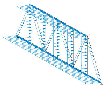
Figure 2. Load diagram for wind on open structures - The program identifies the panels for wind load generation based on the geometry of
the structure. However, the panel identification routine may fail to identify
some open-ended panels (i.e., panels bound by the
ground
at the bottom rather than a member). In this case, you may use multiple, overlapping ranges or member lists to further refine the panel identification.
Controlling Open-Ended Panel Identification
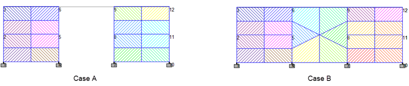
The following structure is a wall with a large door opening. The wind is intended to applied across the entire wall. When a single range is used (Case A) to identify the wind load, the center panel is not correctly identified.

DEFINE WIND LOAD
TYPE 1 WIND 1
INT 0.1 HEIG  12
EXP 1 JOINT 1 TO 3 10 12
LOAD 1 LOADTYPE Wind  TITLE Wind Using Single Range
WIND LOAD X -1 TYPE 1 YR 0 4 ZR 0 12
A series of three ranges which overlap along the global Z direction (Case B) can be used to force the program to evaluate each bay individually.
DEFINE WIND LOAD
…
LOAD 2 LOADTYPE Wind  TITLE Wind Using Overlapping Ranges
WIND LOAD X -1 TYPE 1 YR 0 4 ZR -0.1 4.1
WIND LOAD X -1 TYPE 1 YR 0 4 ZR 3.9 8.1
WIND LOAD X -1 TYPE 1 YR 0 4 ZR 7.9 12.1
Similarly, a series of three wind loads could be added to a load case, each with a member list (or a predefined group of those members) that represent each bay.
DEFINE WIND LOAD
…
LOAD 3 LOADTYPE Wind  TITLE Wind Using Member Lists
WIND LOAD X -1 TYPE 1 LIST 1 TO 4 9 10
WIND LOAD X -1 TYPE 1 LIST 3 TO 6 11
WIND LOAD X -1 TYPE 1 LIST 5 TO 8 12 13General Format for SP 20.13330.2016 Wind Loads
STAAD.Pro can generate both static and dynamic wind loads per the SP 20.13330.2016 code.
Format for the static SP 20.13330.2016 wind load:
LOAD iWIND LOAD { X | Z | -X | -Z } f1 CONFIGURATION k ( NU fNU )TYPE j { XRANGE f1 f2 | YRANGE f1 f2 | ZRANGE f1 f2 | LIST member-list | ALL }Format for the dynamic SP 20.13330.2016 wind load:
LOAD i(mass-data)WIND LOAD { X | Z} f1 WALONG f2 WACROSS f3 ( GL f4 ) ( FRQ ) ( ORT ) TYPE j ( DYN k ) Where:
| Parameter | Definition |
|---|---|
| mass-data | Mass load defined within the dynamic wind load when a separate load case for modal analysis is not previously defined in the STAAD input file. |
| f1 | Correction factor along specified direction. This needs to be used in combination with the WIND LOAD setting. |
| CONFIGURATION k | The configuration used (from 0 to 12) |
| NU fNU | Wind pressure coefficient. |
| WALONG f2 | Effective length of the structure parallel to wind direction. |
| WACROSS f3 | Effective projection of the structure facing the wind direction. |
| GL f4 | Vertical coordinate of ground level. It should be a positive value (zero or greater) defined in current input units. If not provided ground level is automatically calculated from the lowest Y coordinate. |
| FRQ | Optional parameter which results in computation of dynamic wind load vector for all mode shapes extracted from Modal Analysis provided it is within code stipulated frequency limit. Absence of the parameter will result in calculation taking the 1st mode shape only. |
| ORT | Optional parameter to include orthogonal directions in the load case. |
| TYPE j | Wind definition type number. This definition must be of type
SP20 2016. Both static and dyanmic wind loads per the
2016 Russian code use this wind definition. |
| DYN k | Optional parameter that indicates that the wind loading should include the dynamic component determined from the modal response and the static wind load defined in primary load case k. If this option is omitted, then only the static loads from the load definition will be calculated. |
General Format for Russian SNiP 1985 Wind Loads
The format for applying wind loads per the older editions of the Russian codes are as follows:
LOAD iWIND LOAD { X | Z | -X | -Z} f1 CONFIGURATION k ( NU fNU )TYPE j { XRANGE f1 f2 | YRANGE f1 f2 | ZRANGE f1 f2 | LIST member-list | ALL }The value X or Z defines the wind direction. Use of a negative sign defines a leeward wind load.
Where:
| Parameter | Definition |
|---|---|
| f | the wind pressure factor. A negative value defines a reverse wind loading. |
| k | For a SNiP 1985 wind load definition, a configuration parameter defined
for prismatic buildings with a valid range of values is 0 to 12, where these
values represent:
|
| fNU | the wind pressure correlation coefficient. If the parameter is 1, a computed value is used. For rectangular buildings, the calculated value is always used (any input is ignored). |
LOAD COMBINATION command.
Dynamic Wind Load per Russian SP 20.13330.2016
In order to perform dynamic wind load generation in STAAD.Pro you must previously define a static load case. The static load case could be any primary static load case which is defined before the Russian dynamic load case, including a static wind loading per the same code. This static load case will provide static load vector to the dynamic wind load module.
As the Russian dynamic wind
load component requires modal masses and eigen vectors to calculate the dynamic
wind load component at nodes, modal analysis must be performed before the
dynamic wind load definition. Therefore, you must also include a separate load
case for modal analysis with reference mass defined before the load case. See
G.17.3.2 Mass Modeling for details. Alternatively, if the mass loads are not
needed for use with other load cases (that is, a reference load case is not
needed for other loads), then you may define the mass loads within the dynamic
load case prior to the
WIND LOAD command.
The overall wind load effect will be determined by the sum of effects of the static load and an SRSS of all of the contributing modes of the dynamic wind effect which will be used to increase the magnitude of the static load effect.
where
- wm
- mean wind pressure
- wp
- quasi-static wind fluctuation component
STAAD.Pro uses the static wind load and the modal results to create a combined dynamic load from which modal loads are calculated. The modal loads are analyzed and the overall dynamic effect is determined by combining all these with an SRSS combination which is used to increase the effect of the static wind component.