| Load System
|
Loads the active duct system. When selected, and a valid route
is loaded by selecting a source or first component in the route in the view,
opens the
Assign &
Analyze Connection dialog, where flow types are mapped to the available
connection ends. The Load System button turns
 , and remains
animated until one of the mapped ends is selected to process. The route is then
fully loaded with duct section data populated in the summary table. , and remains
animated until one of the mapped ends is selected to process. The route is then
fully loaded with duct section data populated in the summary table.
|

|
When clicked the pointer highlights the duct section row
corresponding to the currently selected segment in the route geometry. Based on
the
Sectioning settings in
Duct Sizing
- Settings, the ducts expanded in a given section are highlighted.
|
| Number Sections
|
Displays the number of sections comprised in the active duct
system.
|
| Group By
|
The filtering and grouping list options are provided for listing
the duct components.
- Duct Section —
Displays the duct components grouped in sections in ascending order. The
collapse/expand arrow icons appears in 2nd column. The summary row above each
section displays the sort criteria and the section number (Duct Section:#),
where # indicates the section number. The heading also displays the summary of
section pressure loss. A single click in Duct Section column heading will sort
duct sections.
- Duct Element —
Displays the duct components grouped in element in ascending order. The
collapse/expand arrow icon appears in 2nd column applicable for entire element
list. The summary row above the elements list displays only heading of the
group by criteria (Duct Element:Duct). A single click in Duct Element column
heading will sort duct elements.
|
| Main Duct Velocity
|
Displays the value set for the Limit Duct Velocity in the Design
Data in Duct Sizing Settings dialog.
|
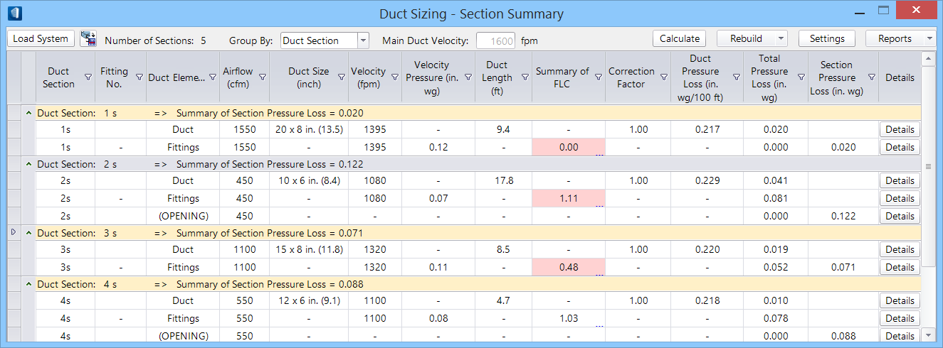
| Duct Sizing Table list
|
The duct sizing table lists various columns that summarise duct
section numbering, fitting identifications, size and dimensions and physical
properties associated with each fitting.
The following are the columns, arranged from left to right.
Note: The unit
mentioned in the parenthesis against applicable properties is in (unit:
Imperial, Metric).
- Duct Section —
Displays the section number in a sequence for the sections in the duct system.
The letter suffixed with the Duct Section number (s, e, r or f) indicates the
flow types mapped during the load. Note that the duct sections list appears in
ascending order only for the
supply flow type, as it's being a
forward flow, whereas for the rest of 3 flow types, it is descending.
- Fitting No. —
Displays the fitting number, labelled or numbered in a sequence for the
fittings in the section.
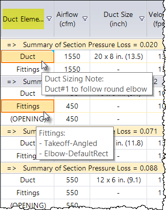
- Duct Element —
Displays the duct element labels, e.g. Duct, Fittings or Opening. When summary
table is viewed using the Group by: Duct Element, a single click in the column
heading toggles the sort order once. Clicking in the cell or simply a mouse
hover displays flyover listing the fitting components in the highlighted
Fittings group (and Note, if any was added to the Duct or Opening cell). These
sub-fittings are mapped and assigned component types when populated in the
Fitting Loss Coefficient Summary (FLC) table.
- Airflow (unit: cfm,
L/s) — Displays the value of air flow for the duct segment in the section. The
value is editable. Prior to calculating, usually the required airflow values
are set at the openings like diffusers in the system. When routing, the Air
Flow property associated components at outlet (Diffuser, Grilles etc.) can be
set via the Parameters in the
Place Component dialog.
- Duct Size (unit:
inch, mm) — Displays the calculated size dimension of the duct. The Width x
Height in case of rectangular ducts and the Diameter for a round duct. Double
clicking in the field opens a drop-down list of options of alternate dimension,
and can be selected that matches the actual size. Right-click and check the
Lock option, if needs to keep one of the sides or both sides dimension or the
diameter constant in computing.
- Velocity (unit: fpm,
m/s) — Displays the derived value of velocity of flow in the section. Click to
edit the value if required or right-click and check the Lock option, if needs
to be kept constant in computing. These values are kept within the Limit Duct
Velocity and controlling the noise level.
- Velocity Pressure
(unit: in wg, Pa) — Displays the velocity pressure computed for the duct
section fittings for a given velocity.
- Duct Length (unit:
ft, m) — Displays the actual length of the duct used in the section.
- Summary of FLC —
Lists the value of fitting loss coefficient for the fittings in the section
row. Double clicking in the column heading or in the Fittings cell opens the
Flow
Loss Coefficient Summary
dialog. The FLC Summary dialog displays the loss
coefficient values of duct component fittings in each section and total loss
coefficient value for the section are listed. The FLC summary table also lists
Parameters used in the loss calculations.
- Correction Factor —
Displays correction factor for the duct elements. For ducts and openings the
correction factor is ideally set to 1, however can be overwritten to alter the
pressure loss. Correction factors for fittings are maintained in FLC summary
table.
- Duct Pressure Loss
(unit: in wg/100ft. Pa/m) — Displays pressure loss value. Applicable only for
ducts. It can be altered to suit optimum duct sizing. Right-click and check the
Lock option, if needs to keep the pressure loss value for the duct section be
unchanged in the calculation. The friction resistance in flow accounts in
pressure loss and the system is ideally aimed to control these values at a
minimum throughout the flow paths.
- Total Pressure Loss
(unit: in wg, Pa) — Displays the value of pressure loss in the total ducts and
duct fittings in the section. For ducts, the default value is computed as the
value of Duct Pressure Loss/100 x Duct Length. The mouse hover for ducts reads
it as "Duct Length*Duct Pressure Loss* Correction Factor". For Openings, it is
the Outlet Pressure property value set for the Parameters in the
Place Component dialog, and for Fittings it is
based on Loss Coefficient value managed in FLC Summary table.
- Section Pressure
Loss (unit: in wg, Pa) — Displays the value of pressure loss in each duct
element. The cumulative pressure loss for a duct section is displayed as
Summary of Section Pressure Loss when viewed Group
By: Duct Section.
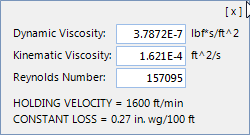
- Details — For each
row the
Details column opens a pull up panel detailing the
values of Viscosities, Reynolds Number and Constant Loss for the selected duct
section/element and additionally the Holding Velocity for the main duct.
This is read only data handy for a quick review. Clicking
[x] closes the panel.
|
| Calculate
|
Calculates the duct sizing by internally computing the flow
rate, velocity parameters against the physical dimension of duct and fittings
lay in the system. Values altered in FLC Summary table and overrides, if any
are reflected in the calculation.
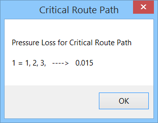
The critical route path report pops up indicating the path
numbers of critical path and the value of pressure drop. The number in the left
side indicates the path numbers and the numbers in the right side indicate
section numbers and the resultant pressure drop. The pressure drop value is
significant for paths having considerable resistance to flow. Clicking OK
dismisses the pop up dialog and the critical path is highlighted in the
geometry. The corresponding section rows in the table also highlighted in
different color shade. Activated Calculate button turns
 , and remains
animated until you click
OK on the Critical Route Path pop up. , and remains
animated until you click
OK on the Critical Route Path pop up.
Note: Ensure a
non-zero air flow values are set to all Openings prior to calculate or
generating any reports.
|
| Rebuild
|
Enabled after Calculation. Rebuilds the active system for altered
parameters set in the duct system, including dimensions of duct fittings in the
duct sections. This is done to achieve a desired Flow Loss Coefficient value.
The geometry and properties associated with the duct system are subjected to
change in the rebuild.
- Write to Model —
Alterations to duct elements after the calculations are written
back to respective duct fittings in the loaded system. This will help to
construct an ideal prototype of standard fittings of desired values that can be
shared across designs in different projects.
- Promote to 3D —
Enabled for single line routes. Rebuild the system with revised values after
the calculations and
promotes the single
line schematic to 3D model. When promoted, the critical route path report pops
ups again ideally with same result of pressure drop value. The host system
remains loaded until the Duct Sizing is unloaded. A copy of single line model
is preserved by adding a prefix
sl to the filename,
<Filename>-sl.dgn in the same path
that of your DGN.
Activated Rebuild button turns
 , and remains
animated until the rebuild (either Write to Model or Promote to 3D) command is
executing. Mismatch in the resized fittings, if any, may cause disconnects and
you will be alerted with the
View
Disconnects dialog. You can locate and delete disconnected center lines
and revise the route for reloading the system. , and remains
animated until the rebuild (either Write to Model or Promote to 3D) command is
executing. Mismatch in the resized fittings, if any, may cause disconnects and
you will be alerted with the
View
Disconnects dialog. You can locate and delete disconnected center lines
and revise the route for reloading the system.
|
| Settings
|
Opens
Duct Sizing
- Settings dialog where design data, size criteria, and reporting
options are set.
|
| Reports
|
Provides options to generate duct sizing reports in different
standards.
- ASHRAE — Generates a
report of duct sizing where duct element and their computed values are confined
to ASHRAE standards.
- SMACNA — Generates
duct sizing report in SMACNA standards covering additional information, such as
Equivalent Dia, Friction per 100ft, and Cumulative pressure loss.
- Check List —
Generates a report that lists all duct elements in the system, their sizes and
values of flow parameters. This type of report is helpful in process where
computed values and intermediate result of duct sizing in the form of report
can be shared with expert authority for approval or advice.
- Sections:
- All — Generates
the duct sizing report showing the effect of critical path along the sections
in the model. The list of path pressure loss is shown in descending order.
- Critical Path —
Generates the duct sizing report specific to the critical section needing
revaluation. This option adds a suggestive note in the footer of the report
(e.g. Required Fan Duty) that hints in resolving the critical pressure loss.
Reports
are compiled and printed in a predefined style (as defined
in Duct Size Settings, Reporting Options). Generated reports can be viewed
online, and using the report toolbar manipulated interactively or exported to a
different format.
|
 Used to compute and based
on pressure, velocity requirements perform sizing algorithms, and rebuild
system after resizing by optimizing route path duct sections.
Used to compute and based
on pressure, velocity requirements perform sizing algorithms, and rebuild
system after resizing by optimizing route path duct sections.