AECOsim Building Designer Help

View Disconnects

Used to manipulate viewing of broken connections or missing flow rates between components after a Resize Connections modification or rebuild in Duct System sizing. Disconnect elements and the corresponding HVAC or Plumbing components can be reviewed and reconnected using the viewing options. The dialog is non-modal so Mechanical discipline modification and manipulation tools can be used while the View Disconnects is open.
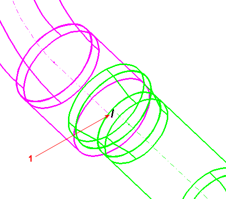
Route components which after a modification or manipulation, have become disconnected, are identified by a special disconnect element generated between disconnected connect points. The disconnect elements by default have their symbology set to color zero, style zero, weight 2, and level name HVAC_DISCONNECTS. The configuration variable HVAC_DISCONNECTSLEVELNAME is available to set the level for the disconnect elements. Disconnect elements are vital for resolving broken routes within a system. Often after duct sizing calculation, a route is rebuilt and written to model. Any mismatch in the resized duct fittings, may induce undesired disconnection in the route, and you are guided to fix it using the View Disconnects interface.


1. A disconnect element is generated between the broken route's connect points.

When disconnections are present, the View Disconnects dialog appears. It is used to manipulate viewing options of broken connections. Disconnect elements and the corresponding HVAC or Plumbing components can be reviewed and reconnected while the View Disconnects dialog is active.
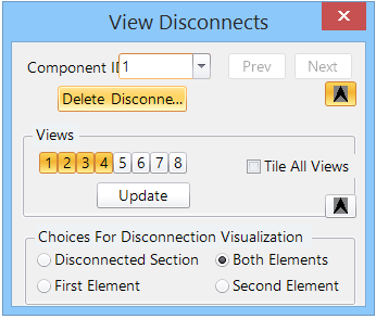

Tip: The View Disconnects dialog also opens if a system is resized, and there is no matching manufacturer catalog item entry for one or more components within that system. The affected components are displayed, and are then customized to fit into the resized system.
SettingDescription
Component ID All disconnected elements are numbered and available in a pull down list for review.
Previous and Next The disconnected elements list can be advanced with the previous and next buttons located to the right of the ID numbers.
Delete Disconnected Centerlines Disconnects are represented by line elements that are generated between the disconnected components' connect points. The Delete Disconnected button removes these elements. A confirmation must be responded to in a secondary dialog.


Note: The Delete Disconnected Centerlines button does not appear when the View Disconnects dialog is opened via an analysis of the system (Locate Missing Flow Rates).
Views The views dialog region controls which of the eight views the disconnected elements are displayed.
  • View buttons — Active views are represented with a depressed button icon when the View Disconnects dialog is initiated. They can then be turned on or off during the re-connection operations.
  • Tile All Views — The Tile All Views check box will arrange the selected views to fit in the application window.
  • Update — Use the Update button to apply the selected view options.
Note: The previous and next buttons also update the dialog settings.
Choices For Disconnection Visualization Four choices are available for visualization. Each option zooms to, fits to the selected views and selects the elements.
  • Disconnected Section — This option views and selects the disconnect element only.
  • Both Elements — This option views and selects both of the disconnected components.
  • First Element — This option views and selects the first disconnected component only.
  • Second Element — This option views and selects the second disconnected component only.
Compact/Expanded dialog Click on the small arrow buttons on the right side of the dialog for expanded or compact versions of this dialog.


Key-in: HVACUI LOAD SHOWVIEWDISCONNECT