Duct Sizing Numbering Scheme
When a duct route is loaded in the Duct Sizing, the summary table populates the duct system data. The system internally assigns unique identification numbers to every duct sections and duct elements within a section. The section numbering is the determined in order of the flow. The next consecutive section number is incremented by 1. The numbering follows internal scheme logical in the direction of flow. .
The Number of Sections indicate the number of duct sections in the currently loaded HVAC System routes.
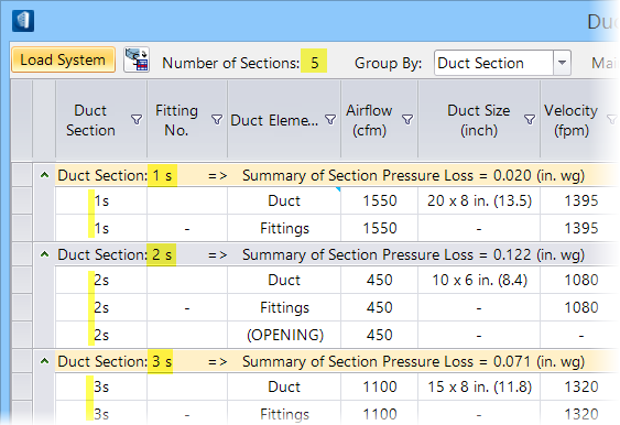
System upon loading navigates the list of route paths and group components to Duct Sections. These sections are tabled in the order of longest route path duct sections to shortest route path duct sections as the sections are divided. Sections are listed in three sub-groupings of components Duct, Fittings, and Openings (Terminals). Fittings are numbered for use with the sub-table Fitting Loss Coefficient in respective sections. For the Fittings category, the component that caused a change in duct section (change in flow, size, or shape) is listed.
- When sorted Group By: Duct Section, the Duct Section column sorts the duct components within the section and summarises pressure loss values for each duct section. Clicking in the Duct Section column heading toggles the order of rows.
- When sorted Group By: Duct Element, the Duct Element column groups the components within the duct category. Clicking in the Duct Element column heading toggles the order of rows.
Clicking in either Duct Section or Duct Element cell highlights the corresponding duct section component in the geometry. The arrow ![]() in the leftmost column indicates currently selected duct section.
in the leftmost column indicates currently selected duct section.
The duct elements within a duct section are identified by per their parent section number. The entire duct elements correspond to duct fittings and are numbered in sequence. These fittings are mapped with ASHRAE Fitting No., as detailed in Fitting Loss Coefficient Summary dialog.