Inline Component Placement
There are two categories of inline components: placeable and slideable. A placeable inline can be automatically located by the router; however, you can place it at any time (before or after initial routing). The location of the component controls the routing of the pipeline as described below. A slideable inline has to be placed initially by the router, but you can slide the inline along the path of the routed pipeline.
Control valves and some user defined inlines are automatically placeable inline components. (Placeable is an attribute of user defined inlines that can be set in the Equipment Library or individually via the Connectivity Editor.) When placeable inlines are automatically located by the router, the segment that the element is placed on is frozen and will dictate the routing of the pipeline. When you move the component, the frozen segment moves as well and continues to dictate future routes of the pipeline. For more on manipulating placeable inline components see "Placeable Inlines".
The remaining inline components are slideable and are not placed until after the pipeline has been routed. For more on manipulating slideable inline components, see "Slideable Inlines".
Although initially categorized as slideable, flow elements can be changed to placeable by moving it or opening the Inline Placement dialog from the Flow Element Editor, or the Connectivity Editor.
Tee Placement
While routing, the AutoRouter places tees (branch connections) in locations that generally minimize the length of the attached pipe. A tee can only be placed in a routed line. Once both ends of a line exist, the AutoRouter may route the pipeline and the Routing Order Controller schedules it for routing. Tee placement takes into account the location of the other end of the connected unrouted pipeline. For headers, tees prefer to be placed in the middle of a segment.
When placing tees, the router removes enough pipe to accommodate the run length of straight tees and reducing tees. Stub-ins, reinforced stub-ins, and olets do not remove pipe length from the run pipe.
The AutoRouter selects the tee type (branch connector) based on the Tee_Types table. (see "Tee Types".) The AutoRouter automatically places tees, reducing_tees, olets, stub-ins, and reinforced_stub-ins. The placed tee type can be changed by you from the Branch Editor.
Tees may be positioned at corners if you have set the Allow Tees at Corners? variable to YES and the size difference is within the Allowable Size Difference. Both Allow Tees at Corners and Allowable Size Difference values are set in the Project Setup (see Tee Placement Constants).
Reducer/Expander Placement
Reducers are placed to maintain sequencing requirements.
Different types of reducers are used in different situations. Horizontal pipe segments use bottom-flat reducers, unless at a pump inlet which uses a top-flat reducer. Vertical segments use concentric reducers. you may override the type and orientation of a reducer from the Inline Manipulator as discussed in "Reducer Manipulator".
Flow Elements Placement
Flow elements are placed just before or after on-pipeway routing. The pipe run, or segment, into which the flow meter is placed is determined by the order of pipeline components in the pipeline.
The preferred placement for a flow element is in a straight pipeline segment that goes from a piece of equipment to a pipeway. To ensure laminar flow in the flow meter, it is placed with sufficient straight piping leading into it. When routing the selected pipe run, the router calculates the required length of the straight run. If the run is too short, the router checks whether routing to the other edge of the pipeway makes the pipe run long enough. If so and if there is space to do so, the router routes the line to the other edge of the pipeway.
As a last resort, the flow element may be located along the pipeway. The final placement in the selected pipe segment is determined by the distance along the pipe segment from the last vertex according to the required straight run.
Flow elements are initially placed as slide components; as such, you can move the element along the path of the pipeline using the Slide tool icon on the Router Toolbox. If you want to provide a specific location for the flow element, they can move the element dynamically in CAD using the Move tool icon on the Plant Toolbox or by entering coordinates in the Inline Placement dialog.
Insuring Laminar Flow
Placement of flow elements depends on laminar flow. To insure laminar flow at the point of placement, the router looks at the lengths and directions of two upstream segments. The four common cases are:
- Option
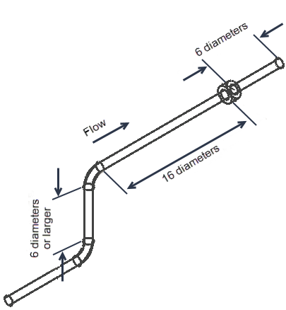
1 – Horizontal, vertical of length six times the pipe diameter or
larger, horizontal in the same direction.
In this case the length of the segment before the flow element is set to a minimum of 16 times the pipe diameter. The length of the segment after the flow element is at least 6 times the diameter.
- Option
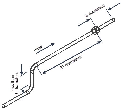
2 – Horizontal, vertical of length less than six times the pipe
diameter, horizontal in the same direction.
In this case the length of the segment before the flow element is set to a minimum of 21 times the pipe diameter. The length of the segment after the flow element is at least 6 times the diameter.
- Option
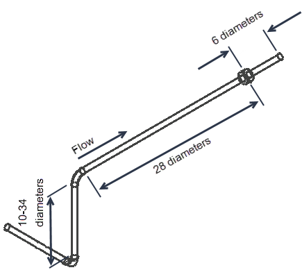
3 – Horizontal, vertical of length
10 to 34 times the pipe diameter or larger,
horizontal in the perpendicular direction.
In this case the length of the segment before the flow element is set to a minimum of 28 times the pipe diameter. The length of the segment after the flow element is at least 6 times the diameter.
If the upstream vertical segment is longer than 34 times the pipe diameter then Option 1 may be used.
- Option
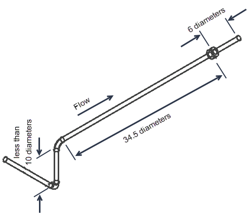
4 – Horizontal, vertical of length less than 10 times the pipe
diameter, horizontal in the perpendicular direction.
In this case the length of the segment before the flow element is set to a minimum of 34.5 times the pipe diameter. The length of the segment after the flow element is at least 6 times the diameter.
If the first upstream segment is also horizontal, the router determines the length of the segment the element is placed on based on either the third or fourth options above.
If the above conditions cannot be satisfied, the flow element is be placed near the pipeline’s origin and lists an exception. If you reposition or modify the flow element, the laminar flow conditions are no longer checked by the AutoRouter.
Control Valve Manifolds
Which equipment the control valve serves – the controlled equipment – is inferred from the ordering of pipeline components in the pipeline. If there is a tee in the pipeline and this pipeline is not an equipment-set header, the control valve manifold is placed in the pipeline between the tee and the equipment it serves.
Control valve placement prefers one side to be clear of obstruction for access to and service of the valve.
The bottom of pipe of a control valve manifold is located 24 in or 600 mm above grade or structure floor. This elevation can be set in the project setup (see Control Valves). If the control valve manifold is connected to a nozzle located less than 3 ft or 900 mm above grade, then the control valve is located at the height of the nozzle.
Control valves are placeable inlines and can be moved dynamically with the Move tool icon on the Plant Tool Box or by entering the location coordinates in the Inline Placement dialog. For more information on placeable inlines, see "Placeable Inlines.".
Control valve manifold dimensions are defined in the "Control Valve Manifold Dimensions" table in Appendix A - Default Data Tables.
By-pass lines on a control valve manifold are not routed.
Pressure Safety Valve Placement
Pressure safety valves (PSVs) are generally placed high and near equipment that can support it. They are placed above either the nozzle or pipeline they are connected to. When the outlet of the PSV is a vent line, the terminus of that line is routed significantly above surrounding equipment.
Both the inlet and outlet pipes of a PSV are non-pocketing routes.
PSVs can be re-located dynamically with the Move tool icon on the Plant Tool Box or by entering coordinates in the Relief Valve Editor (see "The Pressure Safety Valve Editor").
User Defined Inline and Specification Break Placement
User defined inlines are placed according to connectivity requirements. you can define several placement variables in the definition of the inline (see User Defined Inlines) and override those values through the Connectivity Editor.
If the router cannot locate the inline as per your specifications, the inline is placed to meet sequencing requirements and generates an exception. If there is a placement conflict – one inline with a downstream attraction is placed upstream of an inline with an upstream attraction – both inlines are placed with an upstream attraction.
User defined inlines can be slideable (moved along the path of the routed line) or placeable (placed anywhere in a model and the pipe route accommodates that location), their default behavior depends on the inline’s class definition, but it can be over ridden by you on a inline by inline basis. For more information, see "Placeable" or "Slidable".
Specification breaks are placed according to connectivity requirements and are attracted to the component upstream of them.