Inline Component Editors
The inline components with dedicated editors are: control valves, pressure safety valves, tees, and flow elements.
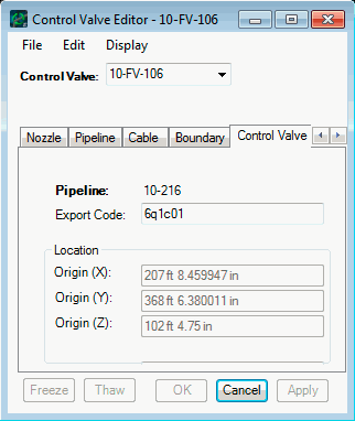
The Control Valve Editor
| Setting | Description |
|---|---|
| Location | If you have moved the valve, there will be a
notation that the valve location is frozen and how it is froze (slide or
placement).
If there is an exception on the placement of the valve, that will be noted. |
| Export Code | The default value of the Export Code is what has been set in the Project Setup. You can change the value in this field so that the currently selected valve has its own export code. |
The Control Valve Editor dialog menus gives you several additional operation:
- Rename the control valve (Rename CV);
- Open the Pipeline Editor;
- Open the Connectivity Editor;
- Open the Inline Placement dialog (Place);
- Open the Inline Manipulator (Slide) dialog (Slide);
- Thaw the position of the control valve;
- Open the Pipeline List;
- Open the Inline List;
- Open the Exception List; and
- Delete a control valve.
The Pressure Safety Valve Editor
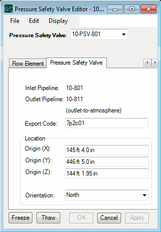
The Pressure Safety Valve Editor allows you to place or relocate a PSV. (Pressure safety valves can also be moved dynamically with the Move button on the Plant Toolbox.)
The Pressure Safety Valve Editor is opened by selecting PlantWise > CAD menu or by selecting the valve with the Edit tool icon on the Plant Toolbox.
Pressure safety valves are different from other inline components in many respects, such as their connectivity and placeability.
| Setting | Description |
|---|---|
| Pressure Safety Valve | Select the desired PSV from the drop-down list. |
| Inlet / Outlet Pipeline | If the connectivity has been defined, the Inlet and Outlet pipelines will be displayed under the Tag field. |
| Location | For the PSV’s placement, you can define: x-origin, y-origin, z-origin, and orientation. |
| Export Code | Similarly, the Export Code for PSVs are treated differently. Where other inlines can have their Export Codes changed in the Inline Placement dialog or the Connectivity Editor, the code for PSVs can be individually changed in the editor. To implement a changed Export Code, click Set. |
| Accept | Clicking the Accept button will freeze the valve’s placement, not the new code. |
If the router has placed the PSV, the Router radio button in the Placed by field in the Position pane will be selected. Once a change has been made and accepted, the User button will be automatically selected.
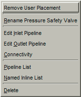
PSV functionality that can be accessed from the menus are:
Menus
PSV functionality that can be accessed from the menus are:
The Flow Element Editor
The AutoRouter Flow Element Editor is mostly for information. Once you select the flow element from the drop down list, the dialog will fill in: the pipeline the valve is located on; where the flow element is placed; the export code.
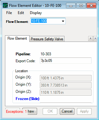
Additionally, if the flow element has been frozen, either by sliding or placing, there will be a notation like that shown in above image. Finally, if there are any exceptions on the placement of the flow element, that will also be noted in the dialog.
Menus- Rename the Flow element (Rename FE);
- Open the Pipeline Editor;
- Open the Pipeline Connectivity;
- Open the Inline Manipulator (Slide) dialog (Slide);
- Open the Inline Placement dialog for the flow element (Place);
- Thaw the location of the flow element;
- Open the Pipeline List;
- Open the Named Inline List;
- Open the Exception List; and
- Delete the flaw element.
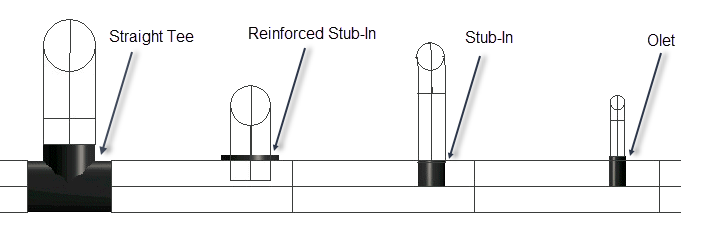
The Branch Editor
The Branch Editor allows you to over-ride the tee (branch) types selected by the AutoRouter.
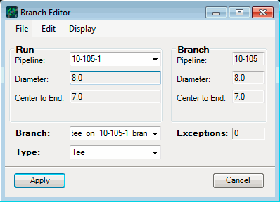
To open the editor, select the tee (or branch connector) with the Edit tool icon on the Plant Toolbox.
The Branch Editor is broken into the following sections: