PlantWise Help

Manipulating Inlines

How an inline component is manipulated depends on if the component is placeable or slide-able.

Placeable Inlines

Control valves and some user-defined inlines are placeable inlines that can be moved dynamically using the Move tool icon on the Plant Toolbox. You can also manipulate the inline from the Inline Placement dialog. This dialog is opened either by selecting a placeable inline after clicking the Modify tool icon on the Router Toolbox, from the edit menu of the inline’s editor, or from the pop up menus in the pipeline and connectivity editors.

SettingDescription
Inline Placement Dialog

You can enter exact coordinates, direction, rotation, and the amount of pipeline segment to partially freeze both up and downstream of the component.

Inline Placement dialog showing a control valve.

The Inline Placement dialog lists the name and class of the inline, the pipeline the component is on, and if the inline has been frozen. Other than the information area, there are several other sections of the dialog:

  • Minimum Segment Distance - These fields allow you to set an amount of aligned piping up or downstream of the inline to be partially frozen. Freezing these segments will not prevent placement of additional inline components (such as reducers on either side of a control valve) within the frozen space. For values entered in these fields, you must click on the Set button. However, so you do not have to freeze the location as well as the segment distances, Freeze does NOT have to be clicked for the new distances to be implemented.
  • Location Description:
    • Origin X, Origin Y, and Origin Z represent coordinates of the placement point of the component.
    • Rotation is the rotation of the component about the direction of the pipeline segment the component is placed on.
    • Direction is the from the upstream vertex to the downstream vertex of the segment the component is placed on.
      • If you select Vector., the Vector region of the dialog becomes enabled and you are to enter the x-, y-, and z-components of the vector that represents the direction of the segment the component is placed on.
  • Command Buttons —Freeze or Thaw the component or Close the dialog.
  • Menus:
    • File - Save Model, Save Model As, and Close the dialog.
    • Edit - Open the Inline Editor, Pipeline Editor, Connectivity Editor, Inline List, or Exception List.
    • Display - Zoom To, Highlight, or UnHighlight the component
    • Route - Route This Pipe, Route This Pipe (w/PWs), or open the Router Control dialog.
Placement of Flow Elements Flow elements can be changed from slideable to placeable by moving it or opening the Inline Placement dialog from the Flow Element Editor, the Pipeline Editor, or the Connectivity Editor.

Initially, the values for the Segment Distances in the Inline Placement dialog is set to an initial estimate of the up- and downstream spacing needed for the flow element. If the flow element has a spacing exception, then the exception message displays the calculated spacing values required for laminar flow (see "Flow Elements Placement" for laminar flow calculations).

Sliding Placeable Inline Components Placeable inline components are not intended to slide. However, you may override that behavior. If you select a placeable inline after clicking the Slide tool icon on the Router Toolbox, PlantWise prompts for confirmation because the placeable attribute of the inline is removed.
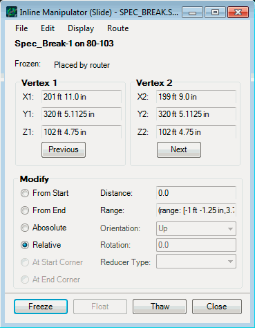
PlantWise prompts you when you try to dynamically slide a placeable inline component.

Slideable Inlines

Reducers, tees, specification breaks, and some user-defined inlines are slideable components. They are moved dynamically (along the pipeline) with the Slide tool icon on the Router Toolbox.

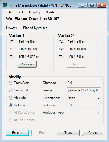
Each of these elements also has a manipulator dialog that can be opened with the Modify tool icon on the Router Toolbox.

The most basic form of the Inline Manipulator dialog is when the inline being manipulated is a specification break. The other manipulators contain additions to this manipulator.

SettingDescription
Specification Break Manipulator The Inline Manipulator for specification breaks has five sections: menus, Vertex 1, Modify, Vertex 2, and command buttons.

Inline Manipulator for Specification Breaks Modify

  • Menus:

    • File - Save Model, Save Model As, and Close the dialog.
    • Edit - Open the Inline Editor, Pipeline Editor, Connectivity Editor, Inline List, or Exception List.
    • Display - Zoom To Vertex 1, Zoom To Vertex 2, Zoom To Segment, Highlight, or UnHighlight the component
    • Route - Route This Pipe, Route This Pipe (w/PWs), or open the Router Control dialog.
  • Vertex 1 - The Vertex 1 area lists the X, Y, and Z coordinates of the up-stream point of the current segment. Also in this area is the Previous button which selects the next up-stream segment.
  • Modify - This area contains a Distance field with a range of legal values listed under it. The value in the Distance field is the amount along the selected segment of pipe that the inline component is moved. The origin of the movement is selected with the radio buttons to the right of the Distance field.
    • From Start – will have the origin of the move be the up-stream point of the current segment of the pipeline.
    • From End – will have the origin of the move be the down-stream point of the current segment of the pipeline.
    • Absolute – requires a coordinate value in either the X, Y, or Z direction (depending on the direction of the current segment.) You need to provide the appropriate coordinate in the Distance field.
    • Relative – is the default. When this button is selected, the inline component is moved from its current position. Positive distance values moves the component down-stream, and negative values move it up-stream.
  • Vertex 2 – This area lists the X, Y, and Z coordinates of the down-stream point of the current segment. Also in this area is the Next button that selects the next down-stream segment.
  • Command Buttons:
    • Freeze – freezes the inline component in the position and orientation selected by you.
    • Float – is not enabled for specification breaks.
    • Thaw – removes user edits to the inline component and returns it to the location calculated by the AutoRouter.
    • Close – closes the dialog. Any changes made since the last freeze will be lost.
Tee Manipulator The Tee Manipulator has the at Corner buttons as well as the Orientation field. The at Corner buttons force the tee to be placed at the corner represented by the selected vertex. The at Corner option only works for interior vertices.

Inline Manipulator for Tees

The Orientation field allows you to select the orientation of the branch. Orientation options are: <default>, Up, Down, E, W, N, S, and Angle. The <default> option allows you to set the location of the tee, but to allow the router to determine angle. Angle, allows you to set the tee to any Rotation about the run pipeline’s axis.

For tees at corners, you can orient the tee so that it points either to the origin (Upstream) or to the terminus (Downstream) of the run pipeline.

Additionally, the Float button allows you to set the orientation of the tee without fixing the location.
Reducer Manipulator

Inline Manipulator for Reducers

Special to the reducer manipulator is the Type field. In this field you can specify concentric, top-flat (eccentric with a top-of-pipe alignment), or bottom-flat (eccentric with a bottom-of-pipe alignment) reducer types. Eccentric reducer types are valid only for horizontal pipe segments.

For reducers, the Float button allows you to set the type of the reducer without fixing the location.
User Defined Inline Manipulator

Inline Manipulator for slideable User Defined Inlines

Like for tees, the user-defined inline manipulator allows you to set the Orientation of the slideable user-inline to Up, Down, E, W, N, S, or to some Angle of Rotation about the run pipeline’s axis.