Pipeline Editor
The Pipeline Editor allows you to inspect and modify the pipeline parameters that control routing.
- Select menu in the PlantWise dialog, (see "Plant Commands"); or
- Select the Edit tool icon in the Plant Toolbox, then select and accept the desired pipeline in the CAD window.
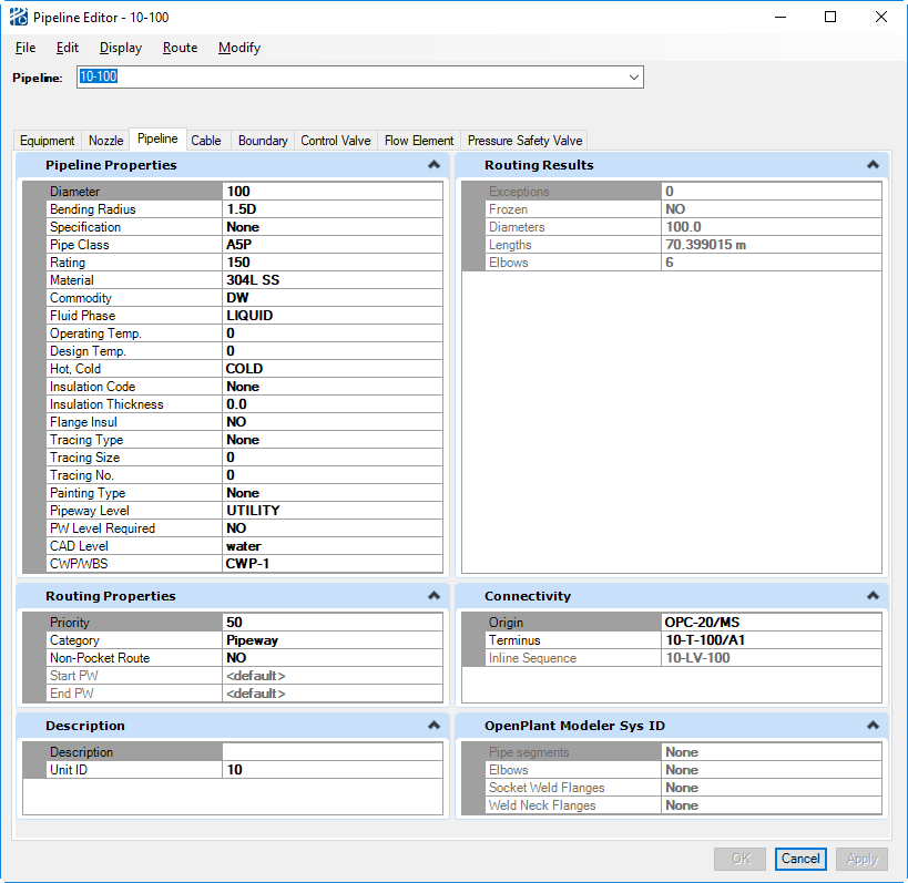
The Pipeline Editor contains a large quantity of information. Most of that information, however, is automatically derived from data tables and the router. You can change most of the values in the Pipeline Editor by either entering or selecting the desired value and clicking Accept. You can select or change the pipeline to be edited from the Pipeline drop down list. Once selected, the dialog fills in with all of the pipeline’s properties.
| Setting | Description |
|---|---|
| Routing Results | The Routing Results section lists pipeline length and number of elbows by diameter. |
| Description | If Comments were provided in the Pipeline List, they are – and can be edited – in the Description field of the Pipeline Editor. |
| Routing Properties | This section shows certain key routing control
variables as well as if there are
exceptions on the pipeline.
 type), un-editable attribute
values are written in dark type), un-editable attribute
values are written in dark
 rather than black. rather than black.
|
| Connectivity | If connectivity has been defined for the current
pipeline, the origin and terminus displays and inline components list in
sequence. You cannot change any connectivity information in the
Pipeline Editor.
|
| Pipeline Properties | The
Pipeline Properties section contains the
pipeline information defined in the
Pipeline List and data table values that
are derived from that definition. For clarity, the attributes that are defined
in the Pipeline List are indicated by
bold type for the attribute name and
type for the attribute value.
|
| User Attributes | From here, you can change the default values of any Pipeline "User Defined Attributes". These attributes are defined in the Project Setup. |
Menus
The Pipeline Editor menus give you access to multiple functions:
The Edit menu gives you access to editors for multiple aspects of the pipeline.
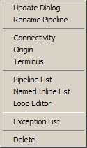
- Update Dialog with new routing results
- Rename Pipeline
- Open the Connectivity editor for the selected pipe
- Open the editor for the Origin of the pipe
- Open the editor for the Terminus of the pipe
- Open the Pipeline List
- Open the Inlines List
- Open the Exception List for the selected pipe
- Delete the pipe.
The Disply menu gives you the ability to:
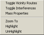
- Turn on/off the centerline representation of the calculated vicinity routes for each end of the pipeline (Toggle Vicinity Routes);
- Turn on/off boxes, drawn on the interference drawing level, that surround pipeline interferences (Toggle Interferences);
- Open the Mass Properties dialog for the selected pipeline;
- Zoom To the pipeline;
- Highlight the pipeline;
- UnHighlight the pipeline.
From the Route menu, you can:
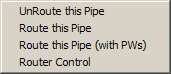
- Unroute the pipe (UnRoute this Pipe);
- Route the pipe without routing the pipeways (Route this Pipe);
- Route the pipe with the pipeways (Route This Pipe (with PWs)); and
- Open the Router Control dialog with just the current line in the Route or Re-Route fields (see AutoRouter Control Dialog ).
From the Modify menu, you can:
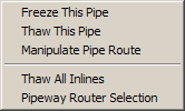
- Freeze the current path of the pipeline (Freeze this Pipe);
- Thaw the pipeline (Thaw this Pipe);
- Open the Segment/Point Manipulator for the selected pipeline (Manipulate Pipe Route) (see "Segment/Point Manipulator");
- Thaw the placement of all the inline components on the current pipeline (Thaw All Inlines); and,
- Select the pipeways used for the route of the current pipeline (Pipeway Router Selection) (see "Editing Pipeway Paths").