Piping
| Setting | Description |
|---|---|
| Concentric Reducer Limit | The size at which horizontal reducers become
eccentric.
|
| Always use frozen route? | Tells the router to always use a previously frozen
direct route even if the endpoints no longer match. The end points will be
connected by a single additional span if necessary.
|
| Default Nozzle Length | The value used for nozzles’ length.
|
| Epsilon | The threshold for comparing whether two numbers are
the same. You should not make this number too large. Values of 1.0e-9 inches
for English projects and 1.0e-7 or 1.0e-6 millimeters for metric models have
proven adequate.
|
| Exception Inlines CAD Level | Determines if user inlines with exceptions should be
drawing on the exception level in CAD.
|
| Exception Pipelines CAD Level | Determines if pipelines with exceptions should be
drawing on the exception level in CAD.
|
| Frozen Inlines CAD Level | Determines if frozen user inlines should be drawn on
the frozen level in CAD.
|
| Frozen Pipelines CAD Level | Determines if frozen pipelines should be drawn on the
frozen level in CAD.
|
| Inline Placement Check | Determines whether you are prompted to verify inline
modification (MOVE as opposed to a SLIDE) when a MOVE is requested.
|
| Temperature Threshold | The value used to determine if a pipe is: HOT or
:COLD based on its input temperature.
|
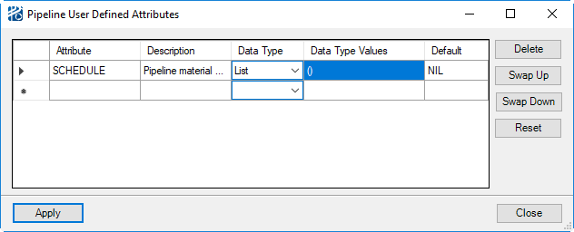
| User Defined Attributes | Opens the Pipeline User Defined Attribute Definition
dialog to add additional attributes that will be associated with every pipe in
the project. These attributes can be reported on and referred to when writing
nozzle placement or vicinity routing rules.
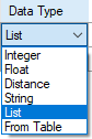
Each Pipeline User Attribute has to have a unique name without spaces or the characters listed in "Invalid Characters ". A more extensive explanation of the attribute can be entered in the Description field. You need not be provides a default value for each attribute. The default value CANNOT be a reference to another attribute.There are six types of information and attribute can be: Datatypes can be selected by a right mouse click in the Data Type field to open the pop up shown below. Attributes are added, deleted, and ordered by using the buttons to the right of the attribute definition area or by using the pop up menu that opens with a right mouse click in the Attribute list. The order of the attributes in the Pipeline User Defined Attribute Definition dialog will be the order they are listed in the Pipeline Editor. |
| Default CWP/WBS Value | The initial value for all pipes.
|
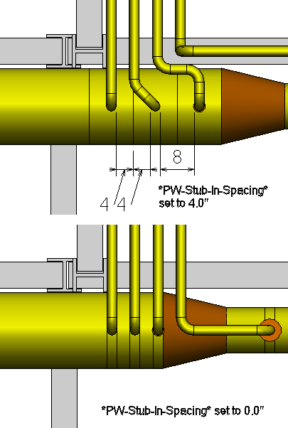
| Stub-In/Olet Spacing | The pipe to pipe distance between stub-ins and/or
olets.
|