The
Segment/Point Manipulator lets you manually
relocate piping or cable segments or vertices. When you move a segment, the
manipulator changes the connecting segments of the pipe/cable to keep the
segments connected and creates additional bends and segments, if required. When
pipeway pipes are manipulated, the pipeline/cable will need to be re-routed.
With the pipeline/cable manipulator, you can place pipeline or cable segments
anywhere; the result is the responsibility of yours.
Segment/Point
Manipulator in Segment and Point modes.
Pipelines and cables can be partially frozen, meaning
that you can choose to freeze just specified segments of a path and to leave
the remainder of the route in the control of the
AutoRouter. When lines/cables are partially
frozen, the frozen segments will remain where they were frozen regardless of
layout changes.
There are multiple ways to open the Segment/Point
Manipulator:
- Select he
Modify tool icon on the
Router Toolbox in CAD and double click on the
pipe or cable to be manipulated;
- Select
menu of the pipeline’s
Pipeline Editor;
- Select
menu of the cable’s
Cable Editor;
- Select
menu of the
Connectivity Editor.
When the manipulator has been opened, the selected
pipeline/cable changes to the highlight drawing level and becomes represented
by a single line.
Regardless of what is being manipulated, pipeline or
cable, segments or points, much of the dialog stays the same.
| Setting | Description |
|---|
| Segment / Point
|
The two radio buttons in the upper left hand corner,
one for segment manipulation and the other for points.
|
| Prev / Next
|
You can scroll through points or segments with the
Prev and Next buttons.
Prev selects the point/segment upstream of
the current one while the
Next moves downstream.
|
| Points List
|
The Points List lists the centerline coordinates of
each vertex of the pipeline/cable. Points are listed from
Origin to
Terminus.
As indicated with the lighter shading of the Points
List, there is a special pop up menu that opens when you click the right mouse
button over that area. This menu simplifies freezing and thawing points and
segments.

- Freeze
this point/segment – marks the selected point or segment frozen;
- Freeze to
Origin – freezes the current point and all points upstream of it;
- Freeze to
Terminus – freezes the current point and all points downstream of
it;
- Freeze to
previously frozen – freezes the current point and all points
between it and the next upstream frozen point;
- Freeze to
next frozen – freezes the current point and all the points between
it and the next downstream frozen point;
- Thaw this
point/segment – thaws the selected point or segment;
-
Thaw to Origin – thaws the current point
and all the points upstream of it;
- Thaw to
Terminus – thaws the current point and all the points down stream
of it;
- Thaw to
previously thawed – thaws the current point and all the points
between it and the next upstream thawed point; and
- Thaw to
next thawed – thaws the current point and all the points between it
and the next downstream thawed point.
|
| Relative Offset
|
You can move points and segments in any orthogonal
direction by any value by entering the value in the
Relative Offset field and then clicking on
one of the direction buttons (N,
S,
E,
W,
Up,
Dn). Once one of the direction buttons has
been clicked, the coordinate of the point or points will be updated in the
points list.
|
| Dynamic – Move
|
Any point or segment can be moved dynamically in CAD
using the
Dynamic Move button. Click the button first,
then grab/drop the desired point/segment in CAD. (The axis lock can help to
improve accuracy.) The previous and next segments will be trimmed or stretched
as needed to accommodate the new location.
|
| Edit - Undo
|
Any actions made since the dialog was opened can be
reversed with the
Undo button found in the
Edit section of the dialog.
|
| Partial Freeze/Thaw
|
A selection of points can be frozen or thawed in the
Partial Freeze/Thaw section towards the bottom of
the dialog.
- Mark
Frozen – a range of points is frozen by entering the numbers to be
frozen (such as
2-5 or
2-5,
7-8) in the
Range field and clicking the
Mark Frozen button.
- Thaw – will
thaw the selected range.
You do not have to partially freeze segments or points that
they have manipulated. As long as the
Freeze button is clicked when all
manipulations are completed, the changes will be implemented and the entire
path of the pipeline or cable will be frozen.
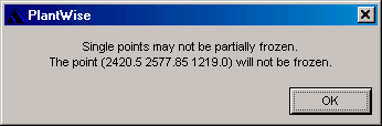
Note: The individual
points are not frozen; rather, the endpoints of segments are frozen. If you try
to freeze a solitary point and not both endpoints of a segment,
PlantWise will prompt you when
the
Freeze button is clicked.
|
| Freeze, Thaw, and Cancel
|
The buttons at the bottom of the dialog are used to:
- Freeze –
confirm all action made (Freeze),
- Thraw – thaw
the pipeline/cable, and
- Freeze – close
the dialog.
|
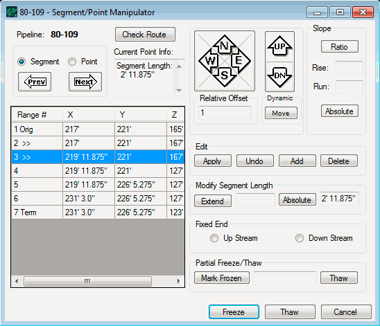
Segment
Manipulator
When manipulating segments, the selected segment is
displayed in CAD with a cylinder surrounding the centerline of the pipe/cable.
The diameter of the segment cylinder equals the nominal pipe diameter or the
outer diameter of the cable.
Segment
Manipulator.
The
Segment Manipulator does not apply
restrictions on which direction you can move a segment. This can mean that new
segments may need to be created (by adding points) depending on the desired
effect of the segment move.
Note: the use of the
>> characters in the
Range # column of the
Points List indicate which two points make up the
current segment.
| Manipulation
|
Procedure
|
| Moving Segments
|
A segment can be moved
directionally or vertically using the
N,
S,
E,
W,
UP, or
DN buttons. The distance a segment is
moved when one of the directional buttons is clicked is
controlled by the value in the
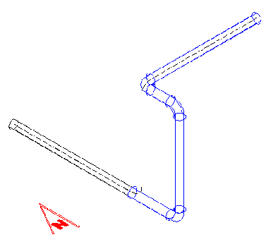
Relative Offset field. The route shown
in the below image
shows the original route that is manipulated for later
examples.
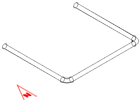
Sample
pipeline.
Routed segments can be moved either in the direction of
or orthogonally to its previous and/or next segments.
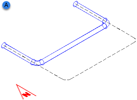 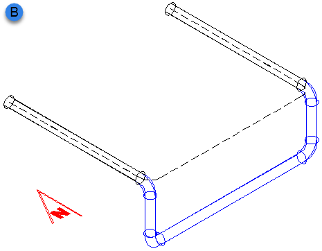
A —
Moving the original east-west segment to the north; or,
B — orthogonally down.
A
shows the movement of a segment in the direction
of its previous and next segments, while
B shows orthogonal movement. Note that
when the segment was moved orthogonally, the necessary connecting segments were
automatically added.
When the previous and next segments do not run
in the same direction the manipulator will add only the segment necessary.
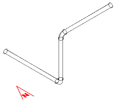 
Vertical segment with previous
and next segments running in different directions. Then movement of the
vertical segment to the south.
If the movement direction is along the direction
of the segment, the segment will be extended in that direction. (For example,
if the
W button is selected for an
east-west running segment, the
western point of the segment will be extended by the distance in the
Relative offset field.)
|
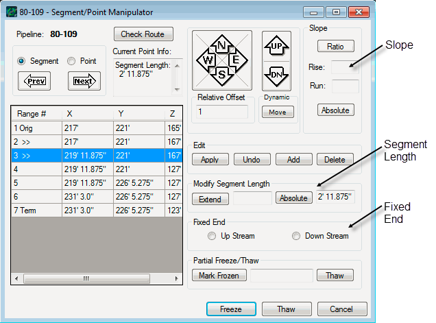
| Changing Segment Length
|
The length of a segment can be changed through
the
Modify Segment Length options. Before
editing the length of a segment, a fixed end must be selected. The
Fixed end radio buttons are to the
left of the
Prev and
Next buttons and fix the point that is
either nearer the origin (Up stream) or the terminus
(Down stream).
To extend the segment a certain amount, enter
that value in the field to the right of the Extend button and click on the
Extend button. To make the segment a
specific length, enter that value into the field to the right of the Absolute
button and click on the
Absolute button.
|
| Adding Slope to a Segment
|
You can enter a slope for the segment in the
Slope input area of the dialog. As with changing a segment length, a fixed end
must be selected before adding slope to a segment.
After filling in values for the
Rise and
Run of the segment, you must check either
the
Ratio or the
Absolute button.
If the
Ratio button is clicked, the values
will be used as a relative slope from the fixed point. For example, if
1 is entered in the
Rise field and
4 in the
Run field the segment will be given a
25% slope from the fixed point.
(Negative slopes can also be input.)
If the
Absolute button is clicked, the values
are taken to be the total horizontal and vertical change in the segment from
the fixed point, and the length of the segment will be altered to meet the new
requirement.
|
| Segments with Reducers
|
In the points list of the
Segment/Point Manipulator, the start
and endpoints of eccentric reducers will be indicated with an R in the left
hand column. Pipeline segments that have reducers in them will be manipulated
as if the reducer points did not interrupt the segment.
|
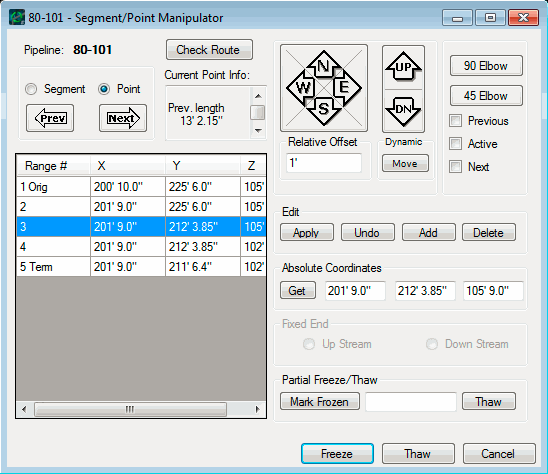
Point
Manipulator
Points are selected with the
Next or
Prev buttons. The selected point is shown with
an expanded segment about the point that has the nominal diameter of the pipe
or the outer diameter of the cable.
The move functions for the point manipulator are the same
as those for the segment manipulator.
The point manipulator will also allow you to edit the
Absolute Coordinates of a point. Individual X-,
Y-, and Z-coordinates can be entered in the fields. Alternatively, a point can
be grabbed from CAD with the
Get button. To change a point this way, first
click on the Get button and then select the desired position in CAD. This will
input the new coordinates in the
Absolute Coordinates fields. No coordinate
changes will be implemented until the
Apply button is clicked.

Elbows of 90° and 45° can be created with the
Point Manipulator using the
90 Elbow and
45 Elbow buttons. When changing an elbow, you
can select which point to anchor so that the correct segments are altered. Most
commonly, you want the previous and next points to stay in their current
location while moving the active point. To do this, the
Prev and
Next or
Prev check boxes are selected and turn off the
Active box. You then just needs to click on the button for the desired elbow
angle. It is possible that the location of the anchored points are too close
together for
PlantWise to create the elbow. If that
is the case you will be notified.
You can also
Add or
Delete points. These buttons are in the
Edit section of the dialog along with
Apply and
Undo. When a point is added in the manipulator,
it is given the same coordinates as the currently selected point and added to
the point list down stream from the original point. The new point can then be
edited like any other.
After making changes with the
Point Manipulator, it is a good practice for
you to Check the route. If the router finds any errors for a point: a flag will
come up in the
Range # column of the Points List next to the point,
and a comment will appear in the Comments about Current
Point field when the point is selected. Common flags are
L (for Length), and
A (for Angle).
Relocating Frozen Pipeline/Cable
Paths
If a change in layout occurs after freezing a pipe or
cable, the pattern of the frozen line can be maintained if:
- both endpoints of the have
moved by the same vector (distance and direction);
- if one endpoint has been
moved parallel to its pipeway approach; or
- if the pipeway has moved
along the same vector of the endpoints.
If an endpoint has moved and does not fall into one of the above
categories, then the line or cable will be thawed and the router will record
the following exception:
Previously frozen <direct, to-pipeway, or from-pipeway>
path is invalid, probably because either one endpoint moved
or both endpoints moved by different amounts. Reverting to
router calculated path.