Pipeway Header Sequence
In general, PlantWise normally berths pipes on pipeways from the outside in, with the largest diameter pipes closer to the outside of the pipeway. Using the Pipeway Header Sequence dialog you can change this behavior for header pipes.
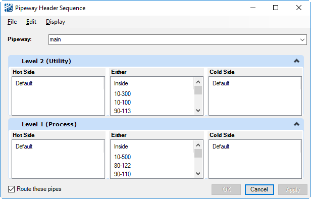
Pipes that start or end on a pipeway are classified as pipeway header pipes. The sequence from the pipeway edge as well as the level can be specified using the Pipeway Header Sequence dialog.
The dialog can be opened from the menu selection from the CAD PlantWise menu. It can also be opened from the - menu selection in the Pipeway Builder dialog.
Menu
- Zoom to Selected Pipe – CAD prompts you to select a view. Once a view is selected the view extents will change to the pipe fills the entire view. The command remains active so data points in subsequent views will zoom those view(s) as well.
- Auto Highlight Selected Pipe – highlights pipes as they are selected in CAD.
- Highlight Selected Pipe – highlightsths selected pipe in CAD.
- UnHighlight Selected Pipe –returns the selected pipe to its normal display.
- Capacity Report – displays the Capacity Report for the currently selected pipeway.
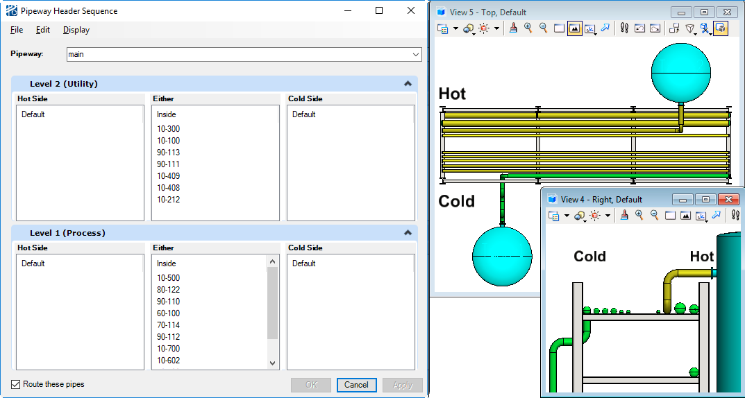
Initially all header pipes will be shown in the Either pane which means the pipes will route using the default behavior. To set which side or level of the pipeway a pipe is to route on, simply click on the pipe tag and drag it to the desired side and level. Multiple pipe tags can be selected for moving by holding down the <Ctrl> or <Shift> keys when making selections.
- Apply saves the sequence and route the pipes if the Route these pipes option is checked and both ends of the pipe can be located. The dialog will remain open.
- OK saves the sequence while the pipes are routed and closes the dialog.
- Cancel closes the dialog without saving the sequence or routing the pipes.
A sample sequence is as shown below:
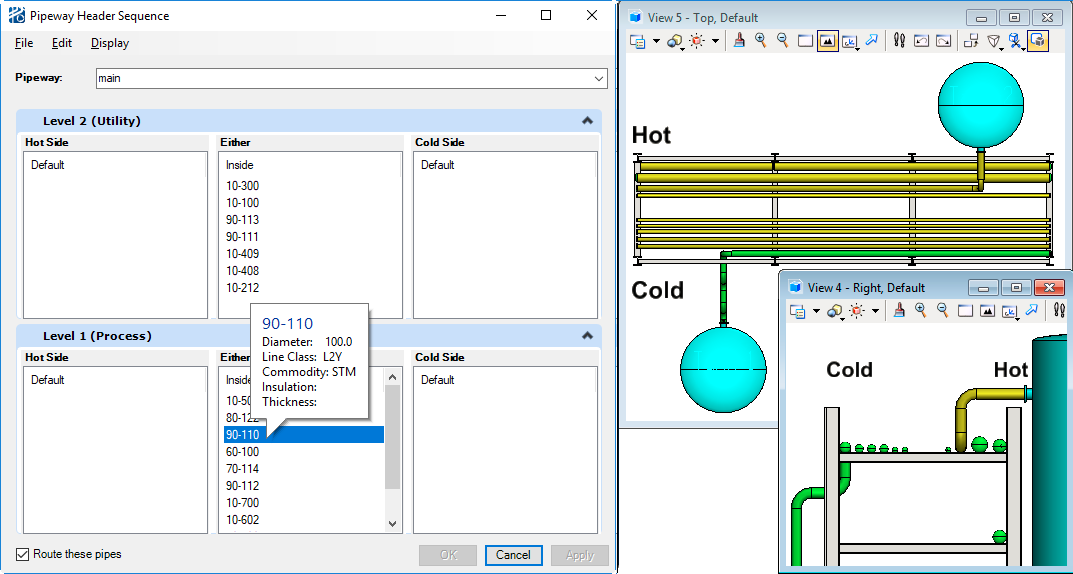
- Pipe tag
- Diameter
- Line Class
- Commodity
- Insulation code
- Insulation thickness
Approach Levels
Drop Zones
Another factor that impacts pipeline placement on a pipeway are drop zones. Outside drop zones allow for pipelines entering/exiting the pipeway to change elevation outside of the pipeway thereby dedicating the most space available to pipeline berthing. Alternatively, inside drop zones allocate some of the pipeway’s width for pipelines to change elevations and berth within the column center line.
The depth of a drop zone varies from pipeline to pipeline. The vertical transition is at least the distance of the elbow center-to-end length plus half the lateral steel width from the column centerline – or beam end if there are no columns. This calculation is, of course, subject to obstacle avoidance.
See also the pipeway Drop Zone Offset in Section Properties of Pipeway Builder.
Pipeline Placement
After berthing and approach levels have been determined, the router runs a series of calculations to determine pipe placement.
Spacing constraints gives you a limited set of placeable networks. For networks, placeable is defined as knowing the side and level of the pipeway the network can be placed on.
The evaluation of the variables mentioned above results in a value for each available network/side combination. The highest valued network is routed, the spacing constraints re-calculated, and then the list is re-evaluated to place the next network.
If, during placement, the current pipeline would overflow a berthing level, the router will stop placement and re-calculate the berthing level for the pipeline with the overloaded level excluded. If all feasible levels are full, then the line will be placed on the original level – generating an exception.
Pipeway pipes are spaced according to the same formula described in "Pipeline Spacing".
Pipes on pipeways are always positioned so that the bottom of the pipe (BOP) is on a routing level (berthing or approach). If there is insulation, the pipe’s centerline is adjusted to allow the insulation or pipe support necessary (see "Pipeline Spacing" for a more detailed description of the bottom-of-pipe offset calculations for insulation).
- when pipeway networks have
been assembled in a way that level transitions are not within one routing plane
(transitions that go through a berthing level);
- this condition is common when you have set variable elevations in Pipeway Builder for a pipeway Levels attributes;
- when pipes are coming from separate secondary pipeways that are directly opposite of each other on the same primary pipeway;
- when the routing plane spacing is not sufficient to accommodate two elbows of large diameter pipes.
Tees on Pipeways
Tees that connect off-pipeway pipelines to on-pipeway pipelines are placed in the on-pipeway line closest to the point where the off-pipeway pipe enters the drop zone. If the pipeline carries a gaseous utility commodity, the tee is approached from above, if it carries a liquid utility commodity, it is approached from below. The fluid phase of the commodity is defined in the Commodity Codes table described in Appendix A - Default Data Tables and may be overridden by you in the Pipeline Editor dialog. Exceptions apply for non-pocketing lines.
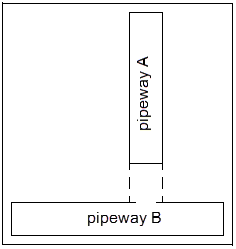
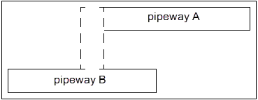
Adjacent Pipeways
Because a pipe’s route can be over multiple pipeways, the pipeway router has to determine a connecting pipeway path during routing. When pipeways (external and structure) are not physically connected, the router calculates if they are adjacent based on the Pipeway Adjacency Threshold, as described in Site Constants. If the distance between pipeways is within this threshold variable, the router routes pipelines through the distance to connect the two pipeways.
- First, two perpendicular structure pipeways.
- Second, two parallel structure pipeways.
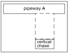
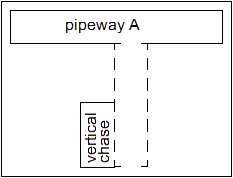
- Third, a horizontal pipeway adjacent to a vertical pipeway or chase when the orientation of the horizontal pipeway is parallel to the orientation of the vertical pipeway or chase.
- Fourth, a horizontal
pipeway adjacent to a vertical pipeway or chase, when the orientation of the
horizontal pipeway is perpendicular to the orientation of the vertical pipeway
or chase.
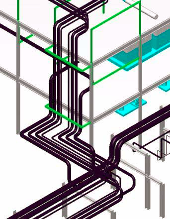
Structure Pipeway Routing
When routing within structures, the pipeway rules (see Pipeway Routing) apply for structure pipeways, vertical pipeways, and vertical chases. As with disconnected external pipeways, the router considers pipeways to be adjacent if they are separated by no more than the Pipeway Adjacency Threshold, as described in Site Constants.
Because routing within structures is more constrained than in external systems, the pipeway router actually creates virtual pipeways that connect adjacent pipeways. Virtual pipeways act like pipeways and are responsible for smooth transitions from pipeway to pipeway.
When connecting structure and external pipeways, the lowest overall approach level must be lower than the highest overall approach level.
Flat Turns
Flat turns may be used when pipes are routing between a vertical chase or vertical pipeway and a horizontal pipeway with perpendicular orientations.
If the flat turn option is on (see "Floor Variables" in Floor Editor) for the floor where the pipeline changes from vertical to horizontal (or vice verse), the pipe segment that runs parallel to the horizontal pipeway will be routed on the pipeway approach level.
If the flat turn option is off for the floor where the pipeline changes from vertical to horizontal (or vice verse), the pipe segment that runs parallel to the horizontal pipeway will be routed on the routing plane immediately above or below the pipeway approach level.