| Component list
|
Located at the top of the Data
tab, the Component list contains HVAC subsystems and components. The Component
list is comprehensive, containing all the EnergyPlus HVAC simulation objects
and their data properties, allowing you to design any conceivable HVAC system
for use in a wide variety of projects.
Components range from individual pieces of equipment
to self contained HVAC systems. Also components may include special objects
used to comply with specific project requirements such as ASHRAE 90.1
Prescriptive Objects.
- Search field —
Located at to top of the Component drop-down list, the search field provides
the ability to reduce the number of components listed making it easier to find
specific components by entering the desired component name or a part of it. The
components list is then filtered to display the search matches. Search includes
sub folders.
- Add — Used to Add
the selected Component to the system being designed. Selecting the Add button
inserts a new property panel below the Components drop-down list in the main
panel of the Data
tab. The newly added component’s full compliment of properties are displayed in
the data panel, and are ready to be edited to suit the current project.
|
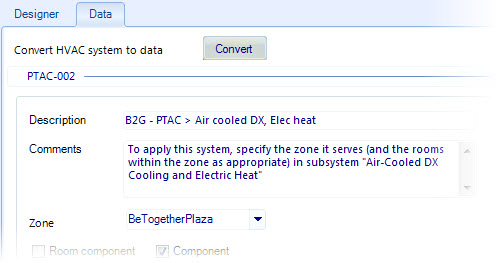
| Convert HVAC system to data
|
Used to convert an HVAC system or HVAC subsystem
created with HVAC
Manager in the Graphic Designer mode of operation (using both the Graphic
Designer tab and Data
tab) to the Data mode (using the Data
tab only). Click
Convert to convert the system. Converting
disables the Graphic Designer mode of operation. A warning appears to confirm
the conversion.
Note: Predefined
HVAC systems and HVAC subsystems and copies of them can only be accessed in the
Data mode of operation (using the Data
tab only).
|
| System Information
|
When a system or subsystem is selected, a panel
appears displaying basic information about the system.
- Description — Used
to enter a description for the HVAC system or HVAC subsystem.
- Comments — Used to
enter comments related to the HVAC system or HVAC subsystem. All predefined
HVAC systems and components are provided with detailed comments that are
intended to assist with applying them to projects.
- Zone — Used to
select a zone for the HVAC system or sub system to be associated with. Zones
are selected from the available drop-down list. Zones must exist before using
the HVAC Manager. Use the
Zone Manager
dialog box to create zones.
|
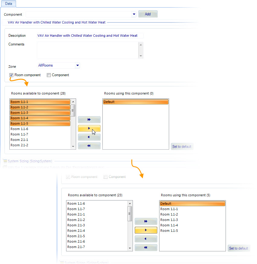
| Room component
|
Used to define the HVAC system or HVAC subsystem as
a room component. When on, an additional settings panel is enabled in which
rooms are selected for the HVAC system or HVAC subsystem to service.
- Rooms available to
component (n) — Displays all the rooms in the selected zone. You can select
individual rooms to move into the Rooms using this component list box.
- Rooms using this
component (n) — Displays all the rooms in the selected zone that are selected
for the room component to be created. You can select individual rooms to move
out of the Rooms using this component list box.
- Move all — Use the
double arrow buttons located between the Rooms available to component and Rooms
using this component list boxes to move all rooms back and forth.
- Move one — Use the
single arrow buttons located between the Rooms available to component and Rooms
using this component list boxes to move rooms back and forth one at a time.
- Set as default —
Used to render the selected room as the default room for adding the room
components to.
Note: When an HVAC
system or HVAC subsystem is designated as a room component, a simplified
graphical representation of the HVAC system or subsystem is added to any room
or all rooms in the zone (selected in the system information panel). The
graphical representation is not a schematic of the HVAC system or subsystem.
Rather, it is an object added to the
OpenBuildings Energy SimulatorProject
Tree
dialog box to the selected room object hierarchy.
|
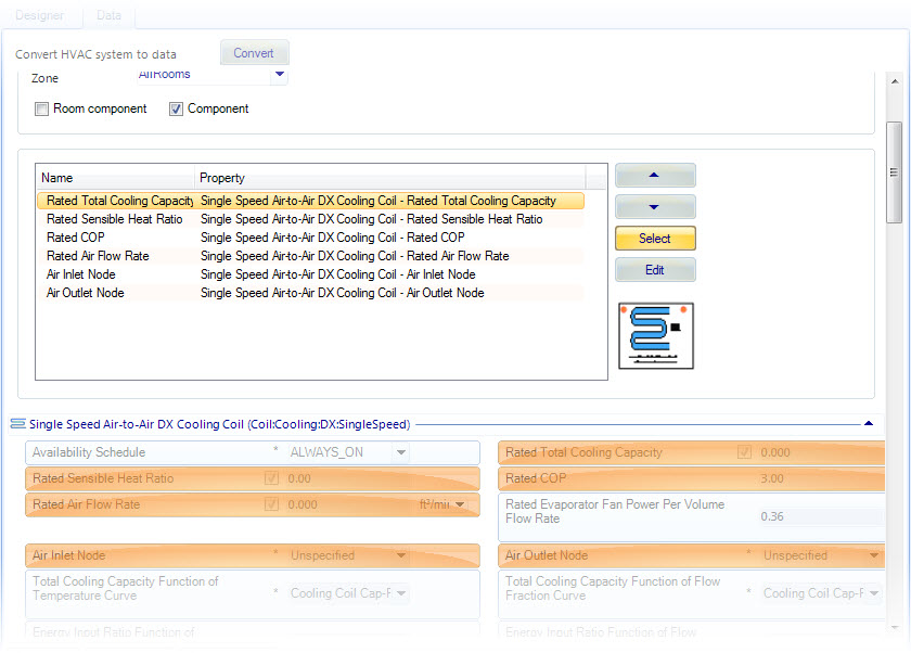
| Component
|
Used to define an HVAC system or HVAC subsystem as
a Component. When on, an additional settings panel is enabled in which the
properties associated with all the HVAC components that make up the HVAC system
or HVAC subsystem (turned component) are listed. The properties are eligible to
be selected for display in the completed compound HVAC component’s properties
panel/dialog.
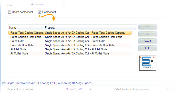
- Component
properties list — Displays the properties of all the base HVAC components that
make up the HVAC system or HVAC subsystem in an ordered list. Property
information is displayed in two columns:
- Name – Displays
the visible property name.
- Property –
Displays the full EnergyPlus object property name.
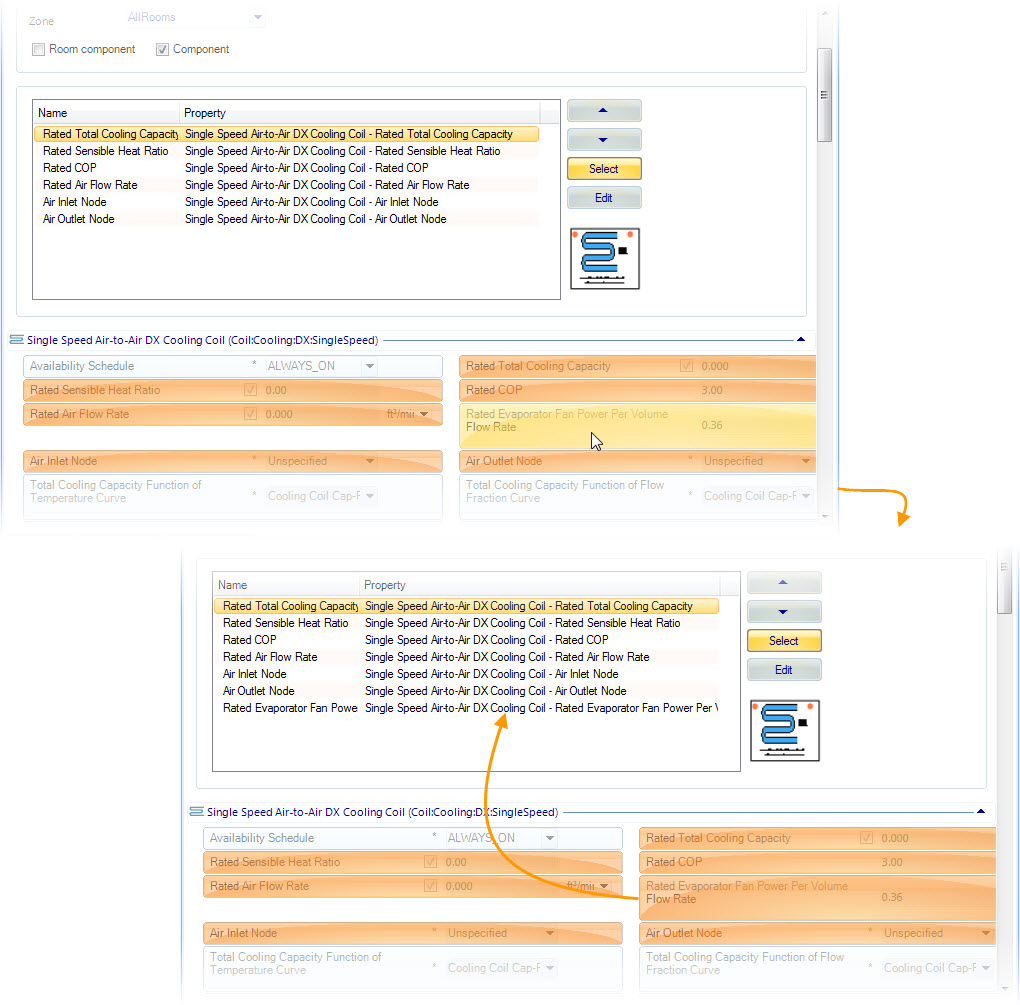
- Up/Down arrows —
The Up arrow moves the selected property up one position in the list each time
it is clicked. Properties at the top of the list are displayed first in the
compound HVAC component properties panel/dialog.The Down arrow moves the
selected property down one position in the list each time it is clicked.
Properties at the bottom of the list are displayed first in the compound HVAC
component properties panel/dialog.
The
compound HVAC component properties panel. Properties are listed in the same
order as in the Component properties list.
- Select — Used to
add or remove properties to the Component properties list. Clicking Select
expands the property panels below the Component properties list for all the
components that make up the new compound HVAC component. Properties already
selected for display (listed in the Component properties list) are highlighted.
Unselected properties are not highlighted. Selecting them highlights them and
adds them to the bottom of the Components list. Conversely, selecting already
highlighted properties removed them from the Component list.
- Edit — Opens the
Component Designer. Component
Designer is used to create graphics for displaying the compound HVAC components
in HVAC
Manager Designer mode including the positions of connection nodes. Typically,
schematic views are used to represent compound HVAC components, but any
representation can be used, including images of actual pieces of equipment.
- Icon — Displays the
graphical representation (schematic) created in Component
Designer.
|
| Available for conceptual design templates
|
When on, the HVAC system or HVAC subsystem is
available in the Conceptual Design project templates. Checking this option adds
the HVAC system or HVAC subsystem to the drop-down list of HVAC systems in the
Step 4: HVAC system section of the
Conceptual Design dialog box
.
|
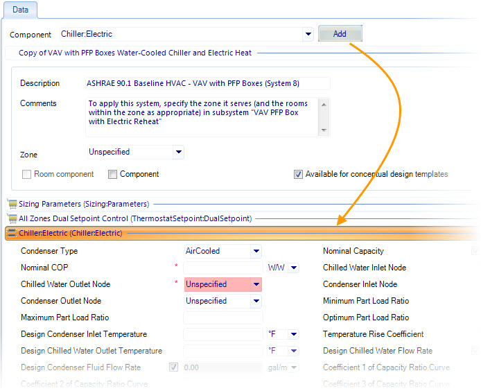
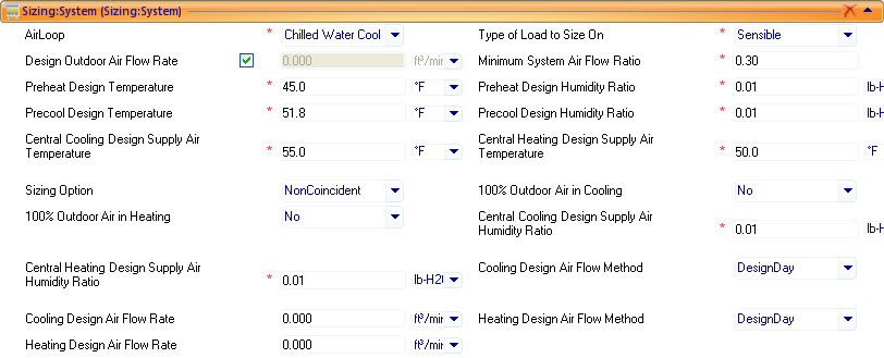
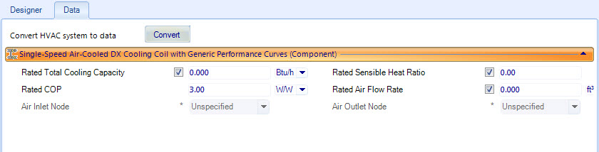
| Component properties
|
When a component is selected and added to the active
HVAC system or subsystem, its data is enabled and available for modification in
a dedicated properties panel.
The objects selected from the Component drop-down
list vary greatly in their properties. EnergyPlus, where the components
originate, provides a comprehensive listing of all EnergyPlus HVAC objects and
their properties. Properties number in the thousands. Detailed descriptions can
be found on the EnergyPlus Input/Output Reference guide.
|
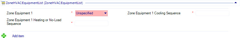
| Components add/remove properties
|
In addition to data properties, certain HVAC
components contain controls used to add more instances of that component.
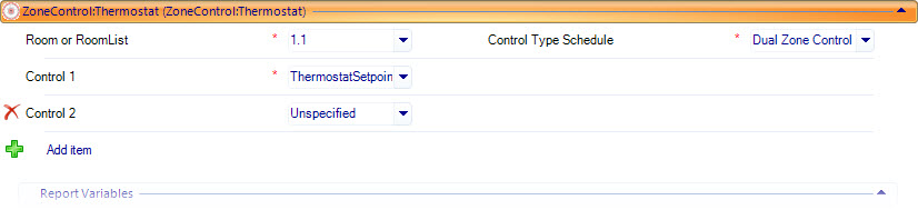
- Add item — Located
at the lower left corner of the HVAC component properties panel, the Add item
button is used to add another instance of the component. In the example
illustrated above, this is an additional controller for the HVAC component Main
Zone Thermostat. Selecting Add item creates the Control 2 item (illustrated
above) with an Unspecified value set for the zone control property drop-down
list. The drop-down list is predefined with the zone controls available in the
project.
- X (remove item)
– Used to delete the additional item added using the Add item button.
- Predefined Data
Values — HVAC component properties by default, are enabled with predefined
values taken from data recorded for those components during tests and other
data collection activities performed by standards organizations such as ASHRAE
and CIBSE.
- Required Properties
— A subset of component properties are required for the HVAC system to simulate
successfully. That is, they must be defined if they are set to Undefined. These
properties are denoted with a colored background and/or a red asterisk
character.
|
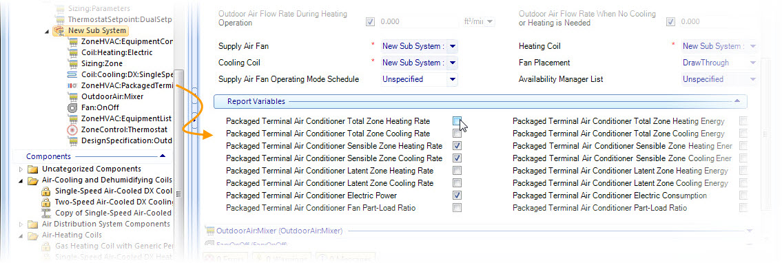
| Report Variables
|
A list of predefined report variables are displayed
in properties panels of all applicable EnergyPlus objects. Checking the report
variables check boxes adds them to HVAC systems reports in the Simulation
results dialog
HVAC tab
.
|
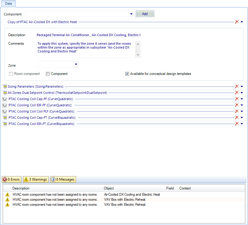
| Notifications panel
|
Used to validate application/project data and
resolve issues with application/project data in real time (as it is being
entered in the data manager dialogs)
via
errors, warnings and
messages.
|