| HVAC system components
|
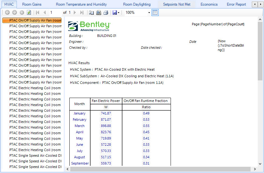
Located in the left panel of the HVAC
tab, HVAC system components can be selected to display their HVAC Results on a
table in the data display panel on the right side of the HVAC
tab.
|
| HVAC System
|
Displays the name of the HVAC system to which the
selected component belongs.
|
| HVAC subsystem
|
Displays the name of the HVAC subsystem to which
the selected component belongs.
|
| HVAC Component
|
Displays the name of the selected HVAC component.
The selected HVAC component’s simulation results are displayed on a table below
the HVAC component.
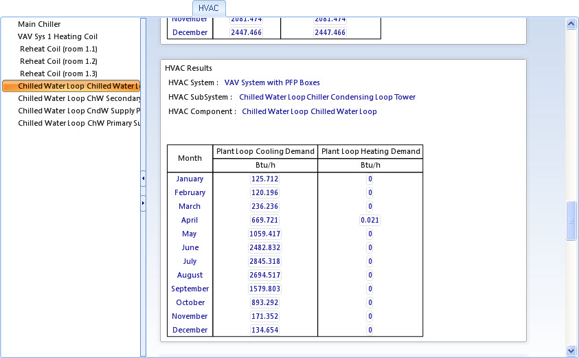
– The following are results for the HVAC system
component Chilled Water Loop:
- Month
– Each table row displays the results for each simulation month for the entire
simulation time period.
- Plant
Loop Cooling Demand – Displays the value of the net demand required to meet the
cooling setpoint of the loop.
- Plant
Loop Heating Demand – Displays the value of the net demand required to meet the
heating setpoint of the loop.
– The following are results for the HVAC system component
Chilled Water Loop ChW Primary Supply Pump:

- Month
– Each table row displays the results for each simulation month for the entire
simulation time period.
- Pump
Outlet Temperature – Displays the amount of heat added to the fluid by the
pump. Due to the fact that a pump is a mechanical device that acts on the fluid
it is circulating, it causes the fluid to increase in temperature.
OpenBuildings Energy Simulator assumes that
all pressure increases caused by the pump are eventually lost due to friction,
and that friction will be added as heat to the fluid. The heat (resulting from
the pump itself and from friction throughout the loop) is added at the outlet
node of the pump.
- Pump
Mass Flow Rate – Displays a calculated Pump Mass Flow Rate based on an internal
variable set when the pump is defined for the HVAC system.
|