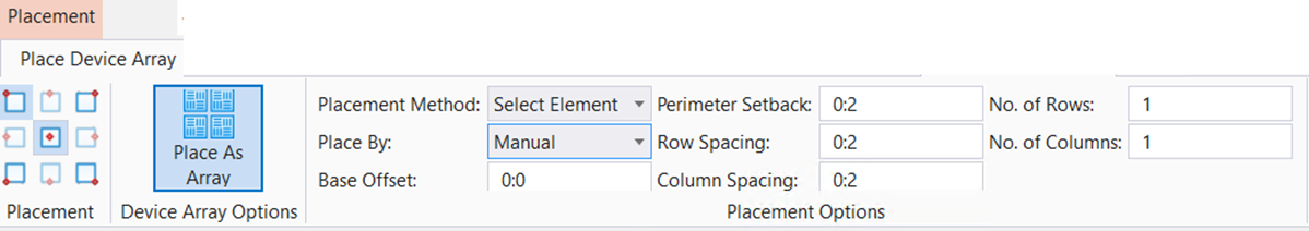
Place Device Array
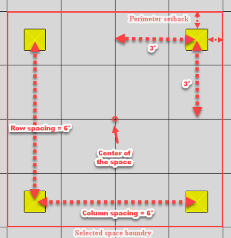
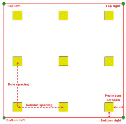
The Place Device Array settings dialog is activated when dynamically placing Mechanical discipline array of components like diffuser array in HVAC, sprinkler array in Plumbing or floor drains array from Drains and Basins. Based on the extent of selected area or Element, the array of currently selected components is created. The devices are equally distributed in rows and columns permissible in the selected perimeter .The tool interface is common to all device array placement tools, and appears when an array placement icon is selected from the ribbon.
- Ribbon:
Building Systems Design
>
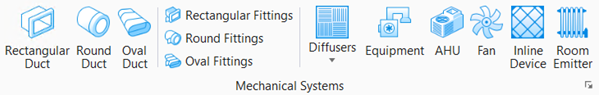
Mechanical > Place Mechanical Systems >
> Diffusers >
 Place as
Array
Place as
Array
- Ribbon:
Building Systems Design
>
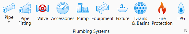
Plumbing > Place Plumbing Systems > Fire
Protection > Place as
Array
- Ribbon:
Building Systems Design
>
Plumbing > Place Plumbing Systems > Drains and
Basins > Place as
Array
Use the Placement settings together with the Place Device Component settings dialog to set user properties like inlet/outlet sizes, component dimensions, flow rates, insulation materials, service type, system ID, and pressure class.
Placement Tabs
Place Device Array - Properties
| Setting | Description |
|---|---|
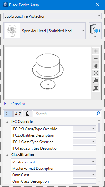
| Catalog Type Selector | Used to select from available Catalog Types. Selections made here updates the Catalog Item Selector combo box. |
| [Default array] | The recent type is assigned as default placing devices -ceiling and floor diffusers and the vertical sprinklers as set in current configuration. |
| Catalog Item Selector |
Used to select from available
Catalog Items. The
Catalog Item Selector combo box contains
several options and settings designed to make it easier to find the exact
catalog item you need to place/change.
The
Catalog Item list also includes user
defined assemblies, and RFA catalog items, if any.
|
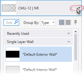
| Catalog Tools |
A split button located to the right of the
Catalog Item Selector contains tools to
assist with managing catalog data prior to placement of selected catalog items.
Note: The
Save Catalog Item tool performs
administrative tasks on DataGroup System catalogs. Administrators and users may
want to hide the tool icon to avoid incidental or unwanted changes to their
firm's dataset by setting the user configuration variables
BB_CATALOGITEM_ADMIN_IN_PLACECMDS
and to "0".
|
| Preview |
Displays the selected catalog item in the preview
window. This display changes and the preview updates as various options are
chosen. The preview also changes dynamically with some of the
prominent settings on the Placement tab, e.g Height, Rotation angle, etc. A
right-click in the Preview opens a
Show/Hide Viewing Tools option menu:
|
| Properties list - toolbar |
Used to manage catalog item properties during
placement or modification. Catalog item properties define the catalog item
instance in the model, and are accountable in the DataGroup System data
management tools. You can place a catalog item with its default property values
or you can change property values as needed, place an instance in the model,
and optionally save the changes to the catalog.
The Properties combo box contains tools for sorting and searching the properties list:
|
| Properties list - tables |
Information in the
Value column rows can be completed by
selecting the applicable cell to activate an editor field, an option menu, or a
pop up dialog. This data is written to the element properties. Properties
displayed with grey text are read only.
The dividing bar between the
Property, and
Value columns can be moved to change the
width of either area. Vertical and horizontal scroll bars are available to
adjust
Properties panel viewing and the display of
data.
Majority of Mechanical discipline properties are provided with schema defined context sensitive options. A downward-pointing arrow icon next to the value field opens a pull-down list of property options. Selecting one of these Context Menu Options opens context menu activated dialog that aids in settings property attributes. The pull-down list also contains Automatic Entry Context Menu Items automatically sets the property without the additional settings or secondary dialog. |
 (
( (
( (
( (
( (
( (
( (
(


 (
( (
( (
(The DataGroup property Mechanical Component Properties provide detailed information regarding applicable entries and ranges of values for each property.
Use the Catalog_Type and Catalog_Item arguments to key-in catalog items directly. For instance BMECH PLACE COMPONENTARRAY SqCeilingDiffuserRect "Square Diffuser Top" where SqCeilingDiffuserRect is the catalog type and "Square Diffuser Top" is the catalog item.