Revolve Feature


Used to construct a parametric solid by revolving an element about an axis. Elements that may be revolved include the following:
- A profile element (line, line string, arc, shape, complex shape, circle, ellipse, or B-spline curve) in the design.
- A set of selected profile elements.
- A multi-line or text element if the text is a True-Type font (*.ttf).
- A planar cell.
- A dimension-driven profile drawn with the Sketch Profile tool.
- A dimension-driven cell in the attached cell library, a cell library in the cell library list (MS_CELLLIST), or another instance of a dimension-driven cell in the active design.
You can use the Modify Profile tool to extract a profile, in order to modify it, or to replace it with another profile. When a dimension-driven cell is used to create the revolved solid, you also can modify the profile's parameters, again with the Modify Profile tool. After modifying the profile, or replacing it, the revolved solid is regenerated with the new values or profile.
| Setting | Description |
|---|---|
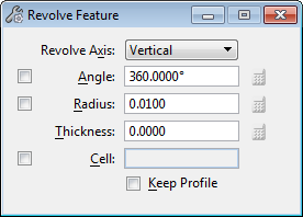
| Revolve Axis | Sets the direction of the axis of revolution.
|
| Angle | If on, sets the rotation angle. |
| Radius | If on, sets the rotation radius. |
| Thickness | Sets the wall thickness of the revolved feature. Positive values produce tubular objects with the wall offset outwards from the profile. Negative values produce tubular objects with the wall offset inwards from the profile. A value of zero produces a solid (non-tubular) object. |
| Cell | If on, the active cell is revolved. A new active cell can be keyed in to the field. |
| Equation icons | Located adjacent to the Angle, Radius, and Thickness settings. Become enabled prior to entering the final data point to create the solid. Those for the Angle and Radius settings require that these settings also are turned on. Opens a dialog that optionally lets you define each setting with variables. For more information, see Variable Driven Modeling and Constraints. |
| Browse Cell(s) icon | (Cell on only) Opens the Select Profile dialog, which lets you select a profile from the attached cell library, or from any shared cells present in the model. Where a dimension-driven cell is chosen, you can edit its parameters. |
| Keep Profile | (Cell off only) If on, the original profile is retained in the model. |

