M. To manually add physical member restraints
To manually add physical member restraints for assignment to physical members, use the following procedure.
Manual restraints apply to steel physical members which will be designed per AS 4100.
Tip: The
restraint details can be automatically generated using a new
Member Restraints item found in the
Utilities ribbon tab in the
Geometry Tools group.

-
For each brace point, specify a fraction of the total physical
member length in the
Brace Location cell.
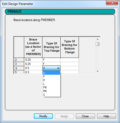
-
Click
Close.
The design parameters are marked with an
 icon. This indicates that the
need to be assigned to members.
icon. This indicates that the
need to be assigned to members.
PBRACE specification is tagged as (Physical), and
therefore can only be assigned to physical members (PMEMBER groups).