M. To add a curved beam
To add a curved beam between two existing nodes, use the following procedure.
Curved members may only be created between two existing nodes. Any non-tapered cross-section is permitted for curved members. The internal angle subtended by the arc must be less than 180 degrees.
Note: The
design of curved members is not supported.
-
On the
Geometry ribbon tab, select the
tool in the
Beam group.

Tip: This tool is contained on a drop-down list below the Add Beam tool.The pointer changes to the Add Curved Beam cursor ( ).
).
-
Click on the start and end nodes, respectively.
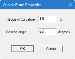
The Curve Beam Properties dialog opens.
-
Type the
Radius of Curvature (in current units of
length) and the
Gamma Angle (in degrees) values.
The gamma angle,γ , is the angle between the member local Y axis and the plane of the circular arc of the member.
