G.4.3 Relationship Between Global and Local Coordinates
Since the input for member loads can be provided in the local and global coordinate system and the output for member-end-forces is printed in the local coordinate system, it is important to know the relationship between the local and global coordinate systems. This relationship is defined by an angle measured in the following specified way. This angle will be defined as the beta (β) angle. For offset members the beta angle/reference point specifications are based on the offset position of the local axis, not the joint positions.
Beta Angle
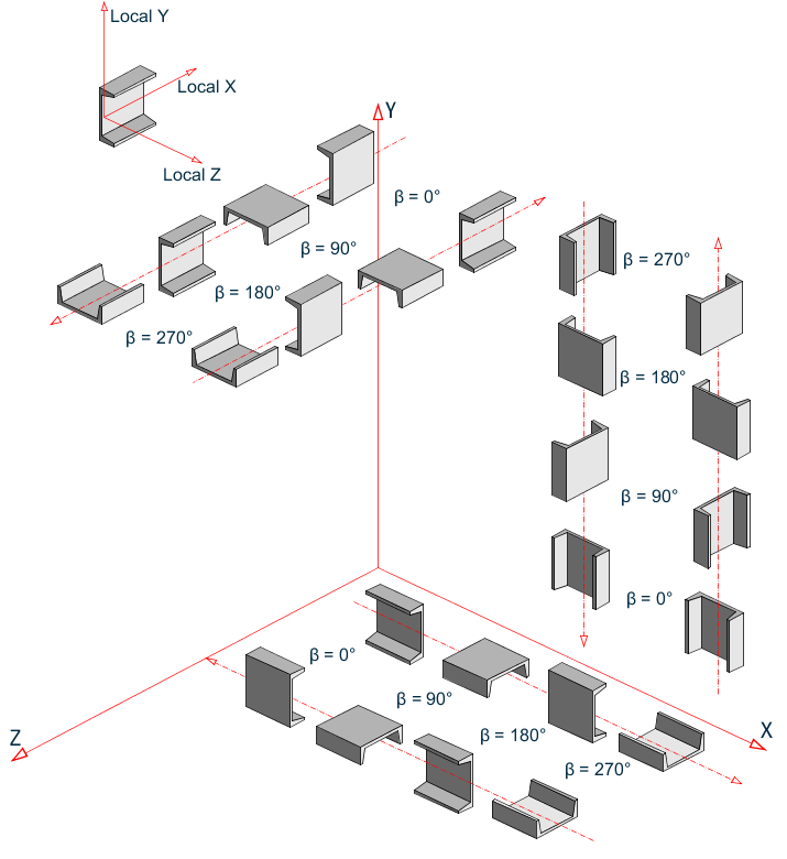
When the local x-axis is parallel to the global Vertical axis, as in the case of a column in a structure, the beta angle is the angle through which the local z-axis (or local Y for SET Z UP) has been rotated about the local x-axis from a position of being parallel and in the same positive direction of the global Z-axis (global Y axis for SET Z UP).
When the local x-axis is not parallel to the global Vertical axis, the beta angle is the angle through which the local coordinate system has been rotated about the local x-axis from a position of having the local z-axis (or local Y for SET Z UP) parallel to the global X-Z plane (or global X-Y plane for SET Z UP)and the local y-axis (or local z for SET Z UP) in the same positive direction as the global vertical axis. Figure 1.7 details the positions for beta equals 0 degrees or 90 degrees. When providing member loads in the local member axis, it is helpful to refer to this figure for a quick determination of the local axis system.
Reference Point
An alternative to providing the member orientation is to input the coordinates (or a joint number) which will be a reference point located in the member x-y plane (x-z plane for SET Z UP) but not on the axis of the member. From the location of the reference point, the program automatically calculates the orientation of the member x-y plane (x-z plane for SET Z UP).
Relationship between Global and Local axes
Reference Vector
This is yet another way to specify the member orientation. In the reference point method described above, the X,Y,Z coordinates of the point are in the global axis system. In a reference vector, the X,Y,Z coordinates are specified with respect to the local axis system of the member corresponding to the BETA 0 condition.
A direction vector is created by the program as explained in TR.26.2 Specifying Constants for Members and Elements. The program then calculates the Beta Angle using this vector.
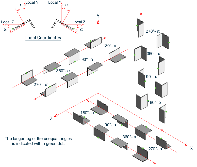
Beta rotation of equal & unequal legged 'ST' angles
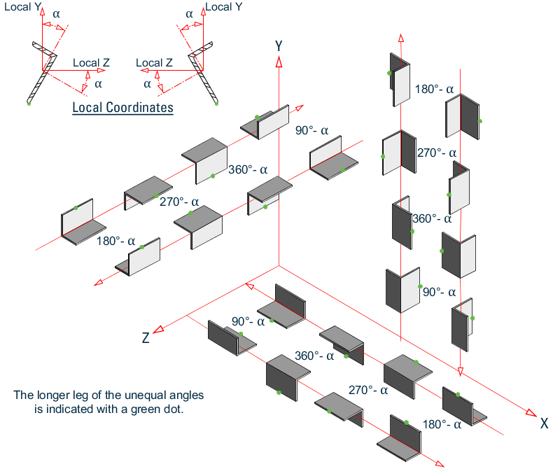
Beta rotation of equal & unequal legged 'RA' angles
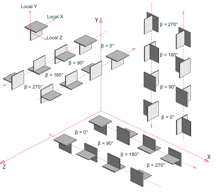
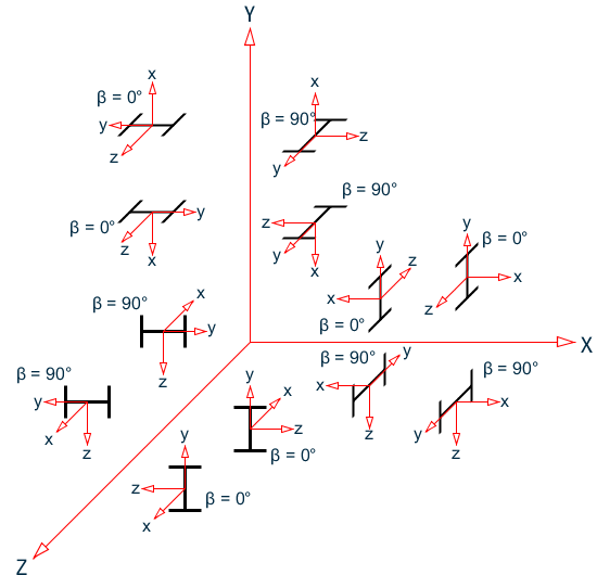
T-shape member orientation for various Beta angles when Global-Y axis is vertical
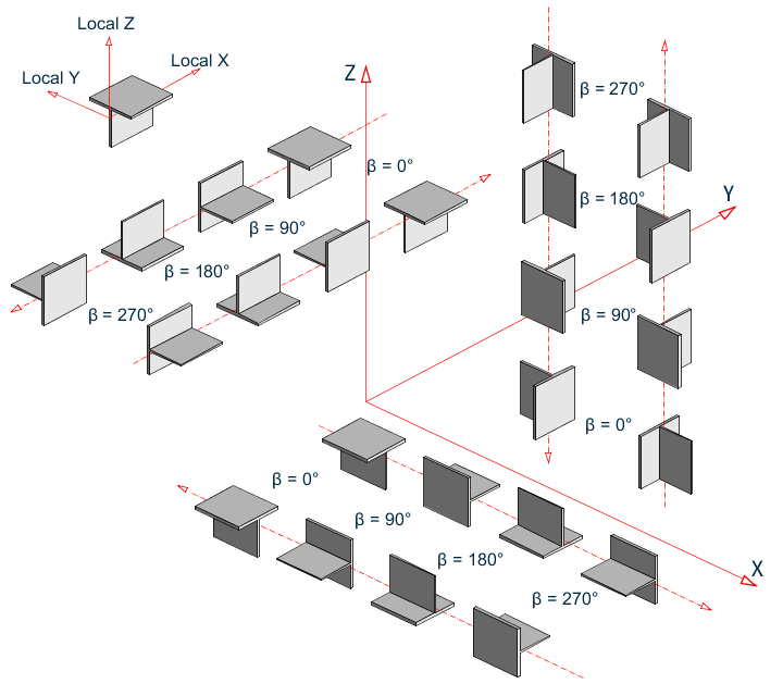
T-shape member orientation for various Beta angles when Global-Z axis is vertical (that is, SET Z UP is specified)