TR.12 Member Incidences Specification
This set of commands is used to specify members by defining connectivity between joints. REPEAT and REPEAT ALL commands are available to facilitate generation of repetitive patterns.
The member/element incidences must be defined such that the model developed represents one single structure only, not two or more separate structures. STAAD.Pro is capable of detecting multiple structures automatically.
Description
The REPEAT command causes the previous line of input to be repeated n number of times with specified member and joint increments. The REPEAT ALL command functions similar to the REPEAT command except that it repeats all previously specified input back to the most recent REPEAT ALL command or to the beginning of the specification if no previous REPEAT ALL command has been issued.
| Parameter | Description |
|---|---|
| i1 | Member number for which incidences are provided. Any integer number (maximum six digits) is permitted. |
| i2 | Start joint number. |
| i3 | End joint number. |
The following parameters are used for member generation only:
| Parameter | Description |
|---|---|
| i4 | Second member number to which members will be generated. |
| i5 | Member number increment for generation. |
| i6 | Joint number increment which will be added to the incident joints. (i5 and i6 will default to 1 if left out.) |
| n | Number of times repeat is to be carried out. |
| mi | Member number increment |
| ji | Joint number increment |
The PRINT MEMBER INFO command may be used to verify the member incidences provided or generated by REPEAT and REPEAT ALL commands.
Example 1
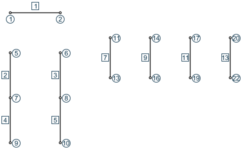
MEMBER INCIDENCES
1  1  2
2  5  7  5
7  11  13  13  2  3
In this example, member 1 goes from joint 1 to 2. Member 2 is connected between joints 5 and 7. Member numbers from 3 to 5 will be generated with a member number increment of 1 and a joint number increment 1 (by default). That is, member 3 goes from 6 to 8, member 4 from 7 to 9, member 5 from 8 to 10. Similarly, in the next line, member 7 will be from 11 to 13, member 9 will be from 14 to 16, 11 from 17 to 19 and 13 from 20 to 22.
Example 2
MEMBER INCIDENCES
1  1  21  20
21  21  22  23
REPEAT  4  3  4
36  21  25  39
REPEAT  3  4  4
REPEAT  ALL  9  51  20
This example creates the 510 members of a ten story 3 x 4-bay structure (this is a continuation of the example started in TR.11 Joint Coordinates Specification). The first input line creates the twenty columns of the first floor:
1 1 21 ; 2 2 22 ; 3 3 23 ; … ; 19 19 39 ; 20 20 40
The two commands (21 21 22 23 and REPEAT 4 3 4) create 15 members which are the second floor "floor" beams running, for example, in the east-west direction:
21  21  22;  22  22  23;  23  23  24
24  25  26;  25  26  27;  26  27  28
…    …    …
33  37  38;  34  38  39;  35  39  40
The next two commands (36 21 25 39 and REPEAT 3 4 4) function similar to the previous two commands, but here create the 16 second floor "floor" beams running in the north-south direction:
36  21  25;  37  22  26;  38  23  27;  39  24  28
40  25  29;  41  26  30;  42  27  31;  43  28  32
…    …    …    …
48  33  37;  49  34  38;  50  35  39;  51  36  40
The preceding commands have created a single floor unit of both beams and columns, a total of 51 members. The REPEAT ALL now repeats this unit nine times, generating 459 new members and finishing the ten story structure. The member number is incremented by 51 (the number of members in a repeating unit) and the joint number is incremented by 20, (the number of joints on one floor).