TR.20.8 Curved Member Specification
The following commands are used to specify that a member is curved. The curve must be a segment of a circle and the internal angle subtended by the arc must be less than 180 degrees. Any non-tapered cross-section is permitted.
General Format
MEMBER CURVED
member-list RADIUS r GAMMA g PRESS p
Where:
- RADIUS r = radius in length units
- GAMMA g = The angle in degrees used to define the plane of the circle. The angle is defined using the same set of rules used to define the orientation (beta angle) of a straight member connected between the two nodes. See Gamma Angle.
- PRESS p = Pressure/Flexibility parameter for pipe bends. See Pressure/Flexibility Parameter .
Notes
- The radius should be in current units.
- Certain attributes like releases, TENSION/COMPRESSION flags, and several member load types are currently not available. Section forces too are currently not available.
- The design of curved members is not supported.
Pressure/Flexibility Parameter
This applies only to pipe bend (elbow) members (OD and ID entered). These members will flex more due to ovalization depending on internal pressure. The ASME Boiler and Pressure Vessel Code, Section III, NB-3687.2, 1971, for Class I components is used to calculate the flexibility reduction factor.
- Set p = 0 or omit for this flexibility increase calculation to occur with internal pressure equal to zero.
- Set p > 0 to specify internal pressure to use in this flexibility calculation. Pressure reduces the flexibility increase.
- Set p = -9999 to ignore this additional flexibility calculation and use only beam theory.
- Set p = flexibility reduction factor (-FLEXF below); which must be a negative number less than –1.0 .
ASME Pipe Elbow flexibility factors theory [ASME Section NB-3687.3]
This section only applies if (Bend Radius/Mean Radius) ≥ 1.70 or if (Arclength) > (2x Mean Radius)
| Flexibility Factor, FLEXF = (1.65x (Mean Radius)2)/[t⋅(Bend Radius)] x 1/[1 + (Press)(Mean Radius)(FACT.)] |
| = | ||
| = | ||
| = | ||
| = | ||
| = | ||
| = |
If the Flexibility Factor computed is less than 1.0, then STAAD.Pro will use 1.0 . The Flexibility Factor directly multiplies or contributes to most non-shear terms in the elbow flexibility matrix.
Notes
-
The input for defining the curved member involves 2 steps. The first is the member incidence, which is the same as that for a straight line member. The second is the command described above, which indicates that the segment between the 2 nodes of the member is curved, and not a straight line.
-
Any non-tapered cross section property currently available in STAAD can be assigned to these members.
-
Currently, two load types are permitted on curved members. One is the SELFWEIGHT load type, described in TR.32.9 Selfweight. The other is the uniformly (UNI) distributed load type of the MEMBER LOAD options explained in TR.32.2 Member Load Specification. The uniformly distributed load has to be applied over the full span of the member. Other member loads such as LINEAR, TRAP, CONCENTRATED force or moment, UNIFORM moment, etc. are not supported.
-
Some of the other member load types such as PRESTRESS, TEMPERATURE, STRAIN loads, etc. are also not currently supported. These options too are expected to become available in future versions of the program.
-
The results of the analysis currently consist of the nodal displacements of the ends of the curved member, and the member end forces. The nodal displacements are in the global coordinate system. The member end forces are in the local coordinate system, with each end of the member having its own unique local axis system. Results at intermediate sections, such as sectional displacements, and sectional forces will be available in future versions of the program.
Gamma Angle
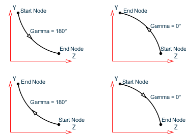
The plane of the circle defines the plane formed by the straight line joining the two ends of the arc, and the local Y axis of an imaginary straight member between those two points. The positive value of the GAMMA angle is obtained using the same sense as the positive value of the beta angle of that imaginary straight line member whose local Y axis points towards the vertex of the arc.
Several diagrams intended to show the GAMMA angle for various segments lying in the three global planes are shown.

Gamma angle for various configurations of the circular arc lying in the global XY plane

Gamma angle for various configurations of the circular arc lying in the global XY plane
Gamma angle for various configurations of the circular arc lying in the global YZ plane
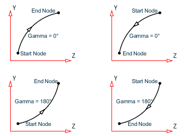
Gamma angle for various configurations of the circular arc lying in the global YZ plane
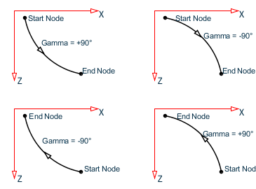
Gamma angle for various configurations of the circular arc lying in the global XZ plane
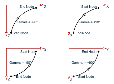
Gamma angle for various configurations of the circular arc lying in the global XZ plane
Member local axis system
The local axis directions for curved members are dependent on the point of interest along the curve. The general rules for local axis, as laid out in G.4.2 Local Coordinate System are applicable. The figure shown later for member end forces indicates the directions of axes at the start and end nodes.
Rotation of local axis
There is a limited facility available to change the orientation of a curved member cross section. The cross-section may be at the default position where the strong axis (local y) is normal to the plane of the curve and the weak axis is in that plane.
The BETA ANGLE and REFERENCE POINT options, explained in G.4.3 Relationship Between Global and Local Coordinates and TR.26.2 Specifying Constants for Members and Elements, are not available for curved members.
Sign conventions
The displacements of the nodes of the curved member are along the global axis system just as in the case of straight members.
The member end forces for curved members are quite similar to that for straight members. The only distinguishing item is that they are normal and tangential to the local axis at the corresponding ends. For example, FX at the start is tangential to the curve at the start node, and FX at the end is tangential to the curve at the end node. Similarly, FZ is along the radial direction at the two ends.
Member releases, offsets, tension/compression, truss and cable may not be specified for curved beams.
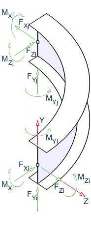
Sign conventions for member end actions; Global Y is vertical
Example
STAAD SPACE
UNIT KIP FEET
JOINT COORD CYL REVERSE
1 150 0 0 13 150 0 90
REPEAT 1 30 0 0
REPEAT ALL 1 0 15 0
MEMBER INCIDENCES
1 1 27 26
101 27 28 112
113 40 41 124
201 27 40 213
START GROUP DEFINITION
MEMBER
_COLUMN 1 TO 26
_CIRCUMFERENTIAL 101 TO 124
_RADIAL 201 TO 213
END GROUP DEFINITION
MEMBER PROPERTIES
_COLUMN PRIS YD 3.0
_CIRCUMFERENTIAL PRIS YD 3.0
_RADIAL PRIS YD 3.0
CONSTANT
E CONCRETE ALL
DENSITY CONCRETE ALL
POISSON CONCRETE ALL
MEMBER CURVED
101 TO 112 RADIUS 150 GAMMA 90.0
113 TO 124 RADIUS 180 GAMMA 90.0
SUPPORTS
1 TO 26 PINNED
LOAD 1
SELF Y -1.0
PERFORM ANALYSIS PRINT STAT CHECK
PRINT MEMBER FORCE LIST 101 113
FINISH