TR.11 Joint Coordinates Specification
These commands allow you to specify and generate the coordinates of the joints of the structure. The JOINT COORDINATES command initiates the specification of the coordinates. The REPEAT and REPEAT ALL commands allow easy generation of coordinates using repetitive patterns.
General Format
JOINT COORDINATES (CYLINDRICAL (REVERSE)) (NOCHECK) (NOREDUCE BAND)
i1 xi1 yi1 zi1 (i2 xi2 yi2 zi2) (i3)
…repeat as needed to define each node or generated set of nodes
(in xin yin zin )
(REPEAT n xr1 yr1 zr1 (xr2 yr2 zr2 … xrn yrn zrn) )
(REPEAT ALL n xt1 yt1 zt1 (xt2 yt2 zt2 … xtn ytn ztn) )
(JTORIGIN xOrigin yOrigin zOrigin)
Where:
| Parameter | Description |
|---|---|
| i1, in | the reference number of the node coordinate that follows |
| xi yi zi | the coordinates of node i in the given coordinate system. |
| Parameter | Description |
|---|---|
| i2 | optional last node number of a sequence of nodes generated from node i1 |
| x2 y2 z2 | the coordinates of node i2 in the given coordinate system |
| i3 | the increment in node number from i1 to i2. The default increment is 1. Each node generated will be equally spaced along a linear path between i1 and i2. |
| REPEAT n | A line starting with REPEAT will generate n copies of the previous line with an offset given by xr1 yr1 zr1. If additional offset values are used (e.g., xr2 yr2 zr2 … xrn yrn zrn), then those offset values will be used by subsequent repeat generations. n is limited to 150 |
| REPEAT ALL n | A line starting with REPEAT ALL will generate n copies of all the previous lines following any REPEAT ALL specification with an offset given by xt1 yt1 zt1. n is limited to 150 |
| JTORIGIN | The optional parameter JTORIGIN causes the program to use a different origin than (0,0,0) for all joints entered with this JOINT COORDINATES command. It is useful in instances such as when the center of a cylinder is not at (0,0,0) but at a different point in space. The JTORIGIN command should be entered on a separate line. After the joint coordinates are entered or generated, then the xOrigin, yOrigin, zOrigin values are added to the respective X, Y, and Z coordinates of each joint. |
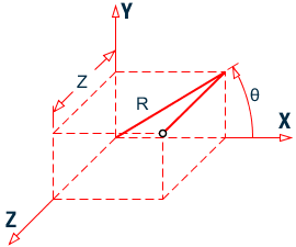
The values of the coordinates (x y z) for cylindrical and reverse cylindrical systems are determined as follows:
- x1 = the radial distance (in current length units) from the origin in the XY plane
- y1 = an angle (in degrees) measured from the global X axis counter-clockwise about the global Z axis
- z1 = the offset distance (in current length units) from the XY plane along the global Z axis
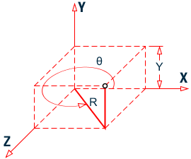
- x1 = the radial distance (in current length units) from the origin in the XZ plane
- y1 = the offset distance (in current length units) from the XZ plane along the global Y axis
- z1 = an angle (in degrees) measured from the global X axis counter-clockwise about the global Y axis
Description
The command JOINT COORDINATES specifies a Cartesian coordinate system. Joints are defined using the global X, Y, and Z coordinates. The command JOINT COORDINATES CYLINDRICAL specifies a cylindrical coordinate system. Joints are defined using the r, q, and z coordinates. JOINT COORDINATES CYLINDRICAL REVERSE specifies a reverse cylindrical coordinate system. Joints are defined using the r, y, and q coordinates. Refer to G.4.1 Global Coordinate System for details and figures.
The multiple JOINT COORDINATES command concept allows UNIT changes and PERFORM ROTATION commands in between; such that these commands would apply to a selected portion of the joints. However, the PERFORM ROTATION command applies to all prior defined joints, not just those in the previous JOINT COORDINATE command.
Example 1
JOINT COORDINATES
1 0 0 0  3 4 4 0  1
| 1 | 0.0 | 0.0 | 0.0 |
| 2 | 2.0 | 2.0 | 0.0 |
| 3 | 4.0 | 4.0 | 0.0 |
Example 2
JOINT COORDINATES
1 0 0 0  5 5 0 0  2
Generates the following three nodes:
| 1 | 0.0 | 0.0 | 0.0 |
| 3 | 2.5 | 0.0 | 0.0 |
| 5 | 5.0 | 0.0 | 0.0 |
Example 3
JOINT COORDINATES CYLINDRICAL
1 10.0 0.0 0.0   5 10.0 180 0.0  1
Generated the following five nodes:
| 1 | 10.0 | 0.0 | 0.0 |
| 2 | 7.1 | 7.1 | 0.0 |
| 3 | 0.0 | 10.0 | 0.0 |
| 4 | -7.1 | 7.1 | 0.0 |
| 5 | -10.0 | 0.0 | 0.0 |
Example 4
The following examples illustrate various uses of the REPEAT command.
REPEAT 10 5. 10. 5.
The above REPEAT command will repeat the last input line 10 times using the same set of increments (i.e., x = 5., y = 10., z = 5.)
REPEAT 3 2. 10. 5. 3. 15. 3. 5. 20. 3.
The above REPEAT command will repeat the last input line three times. Each repeat operation will use a different increment set.
REPEAT 10 0. 12. 0. 15*0 0. 10. 0. 9*0
- six times using x, y and z increments of 0., 12. and 0.,
- and then four times using increments of 0., 10. and 0.