Duct Gallery
Used to place HVAC duct.
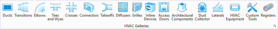
Accessed from the HVAC ribbon:
The following gallery displays which can be left floating or docked to the drawing area.
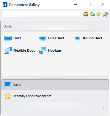
The following table shows the component options in the gallery along with the key in syntax. Selecting a tool from one of the placement galleries activates the Place Component dialog. The generic placement settings, along with the unique set of dimensional and data properties provide the core workflow used to accurately position equipment components in the model.
| Component | <Component Class> in Placement Key In syntax (Mechaddin Place <Component Class> dsc=HVAC) |
|---|---|
Duct

|
HVAC_RECTANGULAR_DUCT |
Oval Duct

|
HVAC_FLAT_OVAL_DUCT |
Round Duct

|
HVAC_ROUND_DUCT |
Flexible Duct

|
HVAC_FLEXIBLE_DUCT |
Hookup Tool

|
Displays the Hookup Tool dialog providing a quick method for you to connect a run of duct or pipe to a terminal device (Grille, Register, Diffuser, Sprinkler heads etc) or a piece of equipment. |
Placement Settings
Select an option from the Duct gallery to display the Place Component dialog. This dialog is common to all HVAC components and allows you define a component's physical parameters as well as general properties before placement. The dialog remains open throughout the placement process.
In the Place Component dialog's Settings tab, select a placement point to determine which port serves as the placement point for the component. The options in the Placement Point list will vary depending on the component being placed. (Available Placement Points for Duct are Main_Port and Run Port.)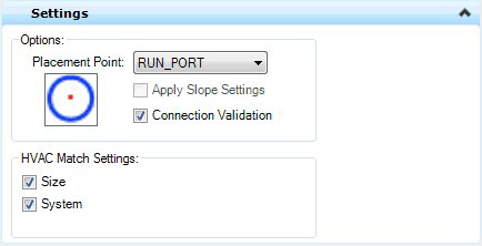
| Placement Point | When placing fittings, branching components and other piping components other than pipe, the Placement Point drop down enables with the following options: |
| Apply Slope Settings | **Applies to Piping components ONLY** |
| Connection Validation | Connection validation performs a validation check based on the joints definition and connection criteria set in the configuration variables. If the connecting components fail this check these are not connected. If this option is turned off, a valid joint is created between component even if they do not satisfy the connection criteria. |
| HVAC Match Settings | The HVAC Match Settings options when enabled
will automatically adopt the Size and System of an existing component in the
drawing when you are connecting to that component. The current values for these
settings as defined in the
Standard Preferences dialog will be overridden.
For example, if you have an HVAC system HVU-HVS-101 set in the Standard Preferences dialog, then you place a new HVAC component to a component on a different system (HVU-HVS-102), using the Match Settings options, then the new component will be placed on the HVU-HVS-102 system and will adopt the same size as the existing component. |
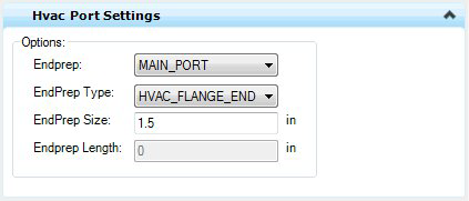
| End Prep | Defines which port to apply the EndPrep Type, Size and Length values to. You are able to define different values for each port if desired. |
| EndPrep Type | HVAC_Flange_End, HVAC_MALE_END, HVAC_Female_End, HVAC_Plain_End |
| EndPrep Size | Enter a size for the EndPrep Type. |
| Endprep Length | Enter length for the selected EndPrep Type. |
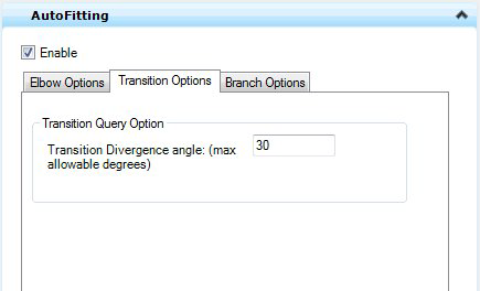
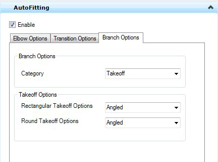
AutoFitting Settings
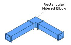
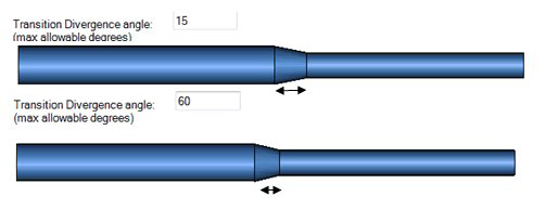
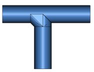
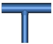
When placing duct, it is suggested to enable the AutoFitting method which will automatically recognize and place components where a change of direction, or a transition is included in the placement process. The AutoFittings settings will define the type of component that will be automatically placed in these situations. Use the tabs displayed below to define the placement options for Elbows, Transition and Branch components using the AutoFitting method.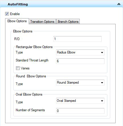
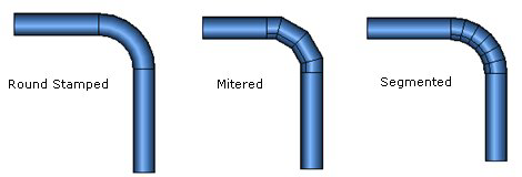 Placement of the Round Stamped
elbow is dependent on its availability in the selected spec. If the size is not
available, the AutoFit function will search for a Mitered/Segmented elbow in
the spec and place accordingly.
Placement of the Round Stamped
elbow is dependent on its availability in the selected spec. If the size is not
available, the AutoFit function will search for a Mitered/Segmented elbow in
the spec and place accordingly.
Placement
To place a run of Duct, pick a start point in the drawing and use the mouse to pick a second point in the drawing to determine the direction and length of the run. You can continue to click data points to route additional segments. Click to Data button to end the duct run. The command will remain active until another command is selected.
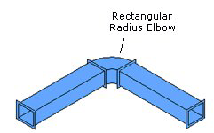
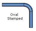
When placing a duct run with a bend, it is suggested to use the AutoFitting method described above. The while you are selecting data points that include a change in direction, or a transition, AutoFitting will use the settings defined to place the correct component type at the location.The Oval and Round duct options will use the bend radius and angle values to search the spec and place an elbow or bend that is defined in the spec. If one is not defined, then no bend component will be placed.
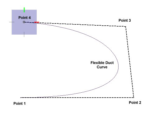
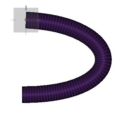
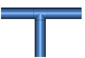
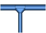
Flexible Duct Curves
With Flexible Duct, you can create curves with the placement using the mouse select multiple data points in the drawing as shown in the left figure below. Note the curve of the Flexible duct that is created when selecting the data points. To complete the placement process, right-click the data button after any data point and the duct will be placed as shown in the figure to the right.
How To