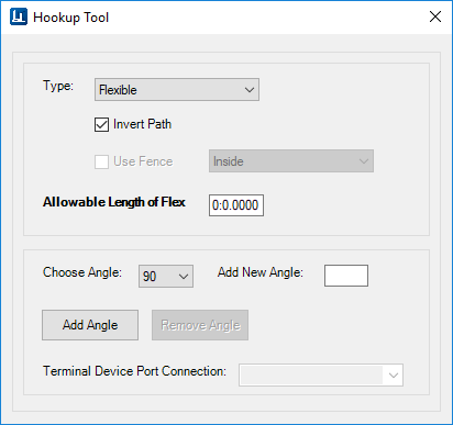
Hookup Tool
 Displays the following dialog
providing a quick method for you to connect a run of duct or pipe to a terminal
device (Grille, Register, Diffuser, Sprinkler heads etc) or a piece of
equipment.
Displays the following dialog
providing a quick method for you to connect a run of duct or pipe to a terminal
device (Grille, Register, Diffuser, Sprinkler heads etc) or a piece of
equipment.
| Setting | Description |
|---|---|
| Type | Select a type of hookup (Flexible or Rigid components). |
| Invert Path |
Enabled: Connects to the top/bottom of the component. Disabled: Connects to the side of the component. |
| Use Fence | If a fence is active, this option lets you use the
fence to select components. If disabled, you can select the components
manually.
If the fence option is used, you can select which fence mode to use: Inside - Selects all of the components which lie inside of the fence perimeter. Overlap - Selects the components that are inside or overlap the fence perimeter. |
| Allowable Length of Flex | This is the maximum allowable length of flex to be used. Remaining path is rigid. If 0 is specified, this is ignored and only flexible duct/pipe is used. |
| Choose Angle | This is the angle of the hookup to the non-terminal
component (duct or pipe). If a 90 deg. angle is specified, a standard takeoff
is placed to make the connection.
If other standard angles are specified (45, 60 etc.), then a lateral is placed in order to route the proper path. |
| Add New Angle | Specify a new angle to add to the list in the field. |
| Add Angle | Adds the value in the Add New Angle text box to the list. |
| Remove Angle | Removes the currently selected angle from the list. |
| Terminal Device Port Connection | This option activates after terminal device such a
piece of equipment with multiple ports is selected. If there is more than one
port, the user can select which port to use. If not, the combo box is disabled.
When you select a port from the box, an arrow indicator is displayed at the selected port in the drawing. |
Using the Hookup Tool
As mention above, the Hookup Tool is used when you want to connect two components which include a terminal type of component such as a register with a run of duct or piping etc. To use the tool, set the type of component you wish to use (flexible or rigid) and use the rest of the settings to define how the hookup is to be created. The table above describes the options in the dialog.
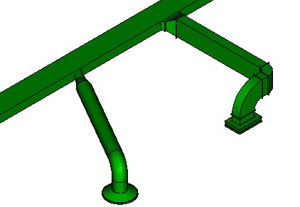
When using rigid components to connect two components the Hookup Tool is designed to automatically place the necessary elbows, transition components, reducers etc. needed to make the connection.
If there is a change in size between the equipment port and the duct or pipe, the second component selected will have the transition or reducer placed at that location.
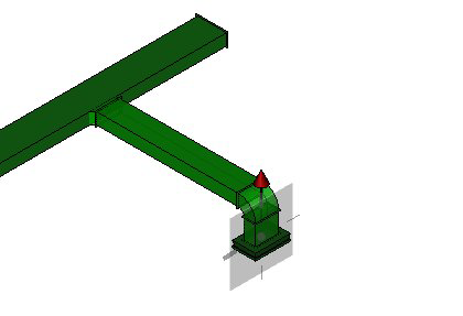
For instance in the following example, a 24 x 12" diffuser was connected to a 30 x 12 run of rectangular duct using rigid hookups. The Angle was set to 90 degrees. In the first image, a straight line connection is made between the diffuser and the duct using a 90 deg elbow and a takeoff from the duct to make the connection.
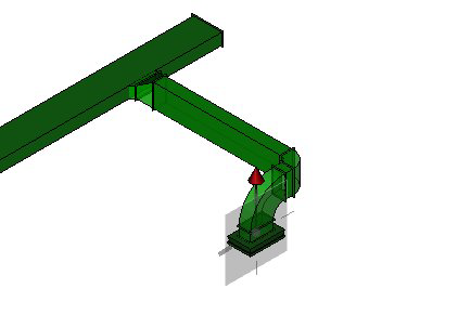
In the next example, the connection point is offset from the diffuser. Because the angle is set to 90 degrees, the hookup is routed in a way to automatically place 90 degree bends.
In the next image, a connection was made between a round diffuser and the same rectangular duct. The angle was set to 60 degrees. Notice how a reducer and a round lateral takeoff are used to make the connection.
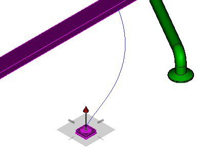
When using flexible type of hookup, when you select the connecting components, a B-spline line displays which is used to route the flexible duct as shown.
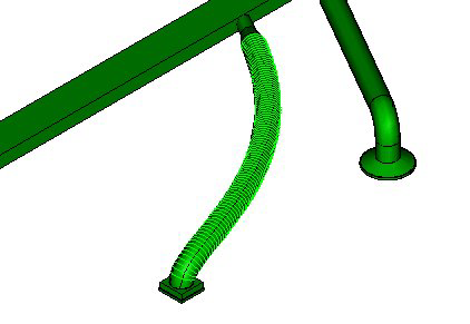
Route the flexible duct as desired and left-click to accept the placement point. Once again, the component used to make the hookup with the flexible duct depends on the size and angle at which it is being placed.
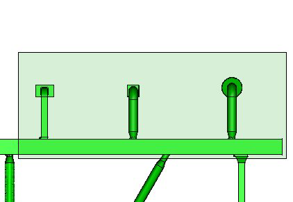
When placing a fence around components, you are able to hookup multiple components simultaneously. In the example below, a fence is placed encompassing the three diffusers and the run of duct.
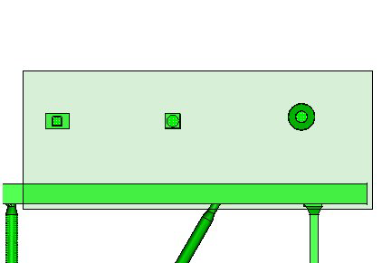
Once you select one of the registers and the duct, hookups will automatically be placed for all of the registers included in the fence as shown below.