Place Component Dialog
When placing a piping component in OpenPlant Modeler , a dialog displays allowing you to define placement information for the component. The placement dialog has two command buttons described below as well as expandable tabs in which you can define placement behavior as well as component properties for the component to be placed.
The dialog is a common dialog which is placed with all Piping/Trayline/HVAC type components. Accessed when: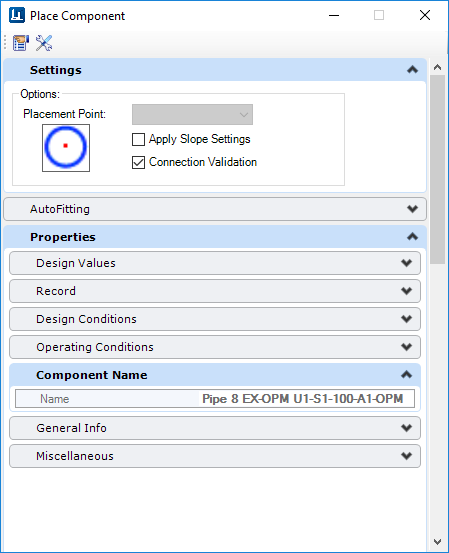
| Setting | Description |
|---|---|
| Match Properties | Prompts you to select an existing component in the model and will place a component with properties matching the selected component, thus overriding the default settings in the Standard Preferences dialog. (For example, if the main size is set to 10" in the Standard Preferences dialog and you click Match Properties and select a 4" tee in the model, the program will pick up the properties of the 4" tee and place a 4" component.) |
| Select Component Instance | This option displays the Spec Selection grid for component that have more than one spec record. Once a spec record is selected, normal placement procedures will apply. If you want to change the spec record, click on the button again to display the grid. |
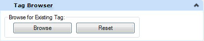
Either of the options above lets you access the tags from your OpenPlant PID drawing and use them when placing 3D components. When you select a piping component for placement, the following Tag Browser section is displayed at the top of the Place Component dialog:
| Setting | Description |
|---|---|
| Browse | Displays the Tag Browser allowing you to search through a list of existing tags that are available for the component class being placed. If you select an existing component tag number, the new component being placed will inherit the component properties associated with the selected tag number. You can opt to rename the tag number for the new component and still retain the inherited properties if desired. |
| Reset | The button will reset the tag number to its original value. |
Settings Tab
This tab provides options relating to the placement points of piping components.
| Setting | Description |
|---|---|
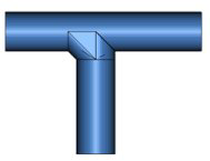
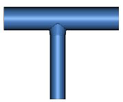
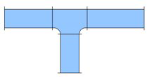
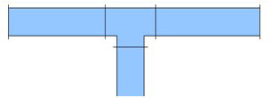
| Placement Point | When placing a length of pipe, the dialog displays as shown above. To determine the placement point for the pipe, use the mouse to select either the center point (as shown) or one of the four corners on the pipe end in the provided bitmap shown below. When placing fittings, branching components and other piping components other than pipe, the Placement Point drop down enables with the following options: |
| Elbow Type (Elbows Only) | When placing an elbow, this drop down list displays allowing you to specify the type of elbow to be placed. |
| Apply Slope Settings (Applies only When Placing Pipe) | The Apply Slope Settings will use the slope
settings defined in the
Apply Slope dialog while routing pipeline components. This
allows the designer to dynamically visualize the affect a slope value on a
pipeline during the designing phase and to possibly make corrections to avoid
clashes with other items.
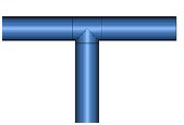
When the Apply Slope option is set, if using the AutoFitting mode, the Allow Misaligned Fittings option will automatically enable and allow rigid bend components, such as 90 deg elbows to be placed if the misalignment is within a set tolerance. By default the tolerance is 10 degrees (+5, -5 degrees on either side of the bend.) |

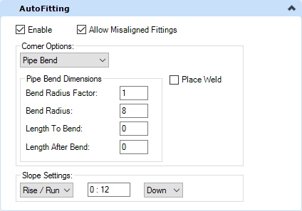
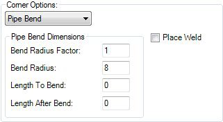
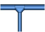
AutoFitting Tab (For Piping Components Only)
The AutoFitting tab shown provides options to define the placement behavior when placing pipe lengths which include bends.
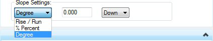 Define a value for the method
selected. Each method will display a different value field in which to enter
the slope value.
Define a value for the method
selected. Each method will display a different value field in which to enter
the slope value.
Properties Tab
This section displays a variety of property tabs which expand displaying editable fields to define the property values of the component. An example is shown below:
| Setting | Description |
|---|---|
| Component Name | Enter the tag number for the component. |
| Operating Conditions | Represent real life conditions that a component will most likely be exposed to. |
| Design Conditions | Specific working conditions the component class was intended to operate in. |
| Model Server Info | Enter Design State for the component. |
| General Info | Properties defining general physical properties of the component being placed. |
| Miscellaneous | Miscellaneous properties pertaining to the component. |
Detail Sketches
The Detail_Sketch property has been added to the OpenPlant3D schema at the DEVICE level, meaning you can define a detail sketch for a specific component to be included when generating an isometric using the OpenPlant Isometric Manager. This property can be defined when initially placing the component, or when modifying one. It is located in the Miscellaneous tabbed section as shown below:
Enter the name of the detail sketch cell into the field to include it when generating an isometric.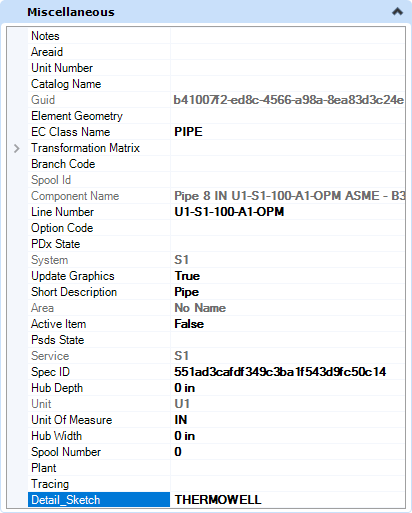
By default, the OpenPlant Isometrics Manager will look to the default cell libraries which are included with install, one of which is named Detail_Sketch.cel. The cell libraries are located in the Cell directory for each isometric style in the project. For example, the IFC style can be found in the following directory:
...\OPModeler_Imperial\DataSet\Isometrics\Styles\IFC\Cell\If you define a detail sketch cell file in the Detail_Sketch property field, that cell must be included in one of the cell libraries or the isometric process will not find it causing an error. If you have existing detail sketches defined in a cell library, you can copy that file into the Cell directory for the isometric style and the Isometrics Manager will find it.
Click Here for a detailed procedure on how to add a detail sketch to a cell library and include it on an isometric.HVAC Specific Placement Options
When placing HVAC components, the following HVAC specific options are displayed in the Place Component dialog.
In the Settings tab, select a placement point to determine which port serves as the placement point for the component. The options in the Placement Point list will vary depending on the component being placed. (Available Placement Points for Duct are Main_Port and Run Port.)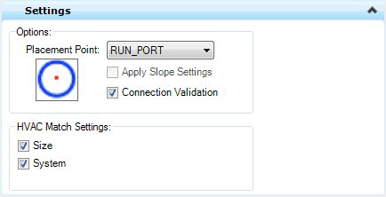
HVAC Port Settings
The HVAC Port Settings tab allows you to define the End Preparations for the ports on the component to be placed. An example is shown below:
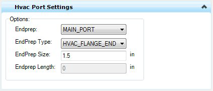
| Setting | Description |
|---|---|
| End Prep | Defines which port to apply the EndPrep Type, Size and Length values to. You are able to define different values for each port if desired. |
| EndPrep Type | HVAC_Flange_End, HVAC_MALE_END, HVAC_Female_End, HVAC_Plain_End |
| EndPrep Size | Enter a size for the EndPrep Type. |
| EndPrep Length | Enter length for the selected EndPrep Type. |
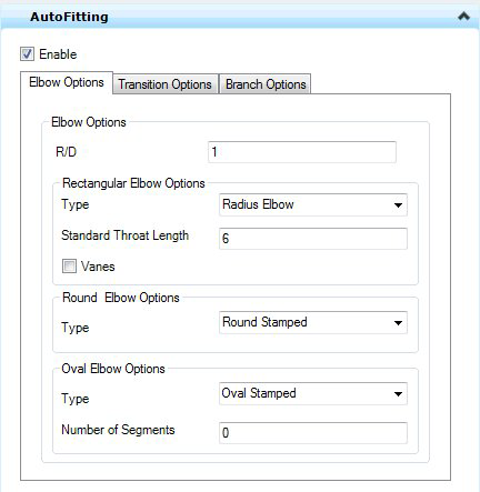
AutoFitting Settings
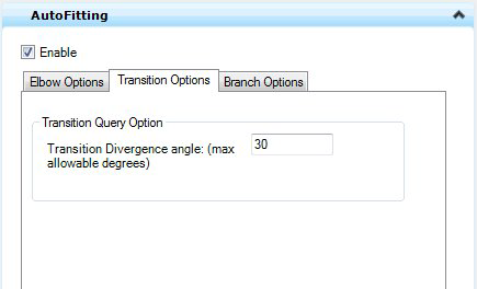
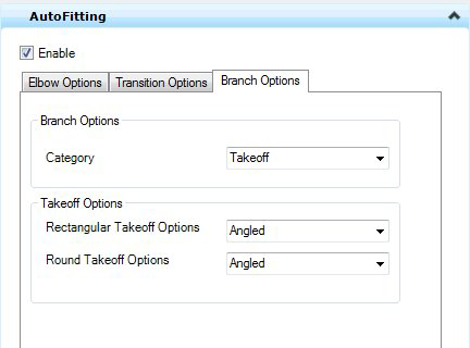
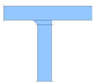
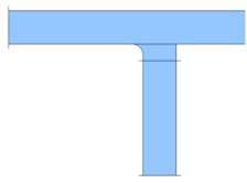
When placing duct, it is suggested to enable the AutoFitting method which will automatically recognize and place components where a change of direction, or a transition is included in the placement process. The AutoFittings settings will define the type of component that will be automatically placed in these situations. Use the tabs displayed below to define the placement options for Elbows, Transition and Branch components using the AutoFitting method.
| Setting | Description |
|---|---|
| Enable | When enabled, all the settings provided in the above AutoFitting interface will be applied when placing the duct components. If the check box is disabled, the AutoFitting rules from the AutoFittingRules.xml file will get applied and all the controls from AutoFitting tab will be disabled. |
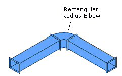
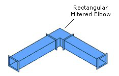
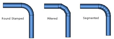
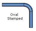
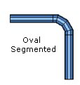
Elbow Options
| Setting | Description |
|---|---|
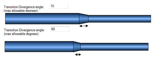
| Transition Divergence Angle | For Transitions (Reducers) should provide option to define maximum allowable divergence angle. If values entered for this exceed this limit transition length should be recalculated according to max allowable angle. |
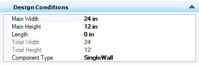
Design Conditions
The Design Conditions tab provides fields to define the physical parameters of the component. The field options will vary depending on the type of component being placed.
Required Values