Standard Preferences
 The Standard Preferences is a
dockable control which displays preferences for either Piping, Equipment,
CableTray, HVAC or Support components (whichever taskbar is currently active).
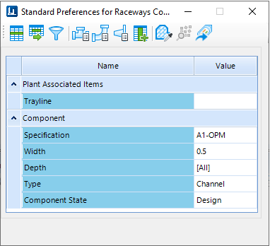
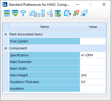
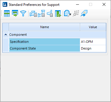
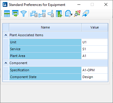
Two different preference types for available. Plant Associated Items are listed
at the top while Component preferences are listed underneath.
The Standard Preferences is a
dockable control which displays preferences for either Piping, Equipment,
CableTray, HVAC or Support components (whichever taskbar is currently active).
Two different preference types for available. Plant Associated Items are listed
at the top while Component preferences are listed underneath.
The title bar of the Standard Preferences control displays the type of Plant/Component preferences listed as shown below:

| Setting | Description |
|---|---|
Use Spec Defaults

|
When a component is selected for placement,
OpenPlant searches the spec for the requested component record. If more than
one match is found, the Spec Record Selection dialog is displayed with a list
of components of the same size and type, but of different end conditions,
schedules, ratings, etc.
When the Use Spec Defaults option is enabled, OpenPlant automatically places the component marked as the default in the specification without displaying the Spec Record Selection dialog. To mark a component as the default selection, Open the OpenPlant Specification Generator application and place a 1 in the Option Code field of the default component's specification record. |
Reload Specs

|
This option will reload the specs folder during the modeling session. So in case the spec has been modified in any way, you are able to reload the spec to include any changes. |
Filter Spec On/Off

|
When on, the component gallery will only show items that are in a specification. |
Use Auto Branch Table

|
When enabled, whenever there is a branching
connection in
OpenPlant Modeler
, the branching component defined in the Branch Table for the
specific run and branch size will be placed.
The Branch table is populated using the Branch Editor in the OpenPlant Specification Generator included with the OpenPlant Project Administrator install. |
Use Auto Elbow Table

|
When enabled, whenever there is a bend connection
in Modeler, the Bend component defined in the Auto Elbow Table for the specific
run and branch size will be placed.
The AUTO_BEND table is populated using the Auto Elbow editor in the OpenPlant Specification Generator included with the OpenPlant Project Administrator install. |
Use Auto Flange Table

|
When enabled, whenever there is a flange connection
in Modeler, the Flange component defined in the Auto Flange Table for the
specific run and branch size will be placed.
The AUTO_FLANGE table is populated using the Auto Flange editor in the OpenPlant Specification Generator included with the OpenPlant Project Administrator install. |
Show Spec Grid

|
This option is only used when multiple components are defined for a branch size in the Branch Table. In this case the Spec Record Selection dialog displays allowing you to select which branch component to place. |
Auto Match

|
Enable this option when connecting components to
existing components in the drawing. This option is similar to the Match
Properties option described above, except it will automatically match the
properties at you a select an existing component in the drawing to connect to.
When you select a component to connect to, the Spec Record Selection dialog will display if there is more than one record in the spec that matches the size and type of the existing component. Select the correct record from the dialog to continue with the placement. |
Allow MRULookup

|
When enabled, this option (Most Recently Used
Lookup), will preserve recently used/updated settings in the Standard
Preferences, Place Component or other dialogs where the user may change these
settings.
When you place a component, the values in the Place Component dialog will be populated according to the Standard Preferences. When placing a component in non-spec mode, and this option is enabled, then the last placed value will be used. |
Import Tag Instances

|
Lets you import pre-defined Tag Instances from an external file
into the current drawing. The following file formats are supported:
Displays the Import Instances dialog where you can view/select which tag instances to import. |
| Plant Associated Items | Organized in the upper part of the control. These are relationship preferences (e.g., Pipeline, System, Unit). These preferences are used throughout the application to provide quick component selection for updates, reporting, etc. By default, only the Pipeline preference is listed as a default. Select a value from the drop down list, or you can select New from the list to display the Create Pipeline dialog to define a new pipeline value. |
| Component Preferences | Organized in the lower section of the control.
These are the most common component preferences that define the default values
for components to be placed.
The following preferences are available:
|