| Hierarchy pane |
The Hierarchy pane is located on the left of the Raster Manager dialog and displays the hierarchy of the files in a tree view. The following rules apply, assuming that the three plane toggles (View > Background Plane, Design Plane and Foreground Plane) are on and that a DGN is opened.
- Show Reference Hierarchy:
- If the active design is selected in the Hierarchy pane: Only rasters attached to the active design are listed in the Image List box.
- The functions bring to front, send to back, bring forward and send backward are available for rasters not in the Design Plane. The scope of these functions is limited to the plane of the selected raster(s). If rasters from more than one plane are selected, the functions are not available.
- The drag-and-drop functionality is active. It is possible to drag to and from the Background Plane and the Foreground Plane. When the raster is dropped, it will be moved only if the destination is valid. If the destination is invalid, a message explaining the error displays in the message center.
- If a referenced DGN is selected in the Hierarchy pane: Only the rasters attached to that DGN are listed in the right pane.
- The functions bring to front, send to back, bring forward and send backward are not available.
- The drag-and-drop functionality is not active.
- Flat Mode:

- Active design is selected in the Hierarchy pane: All rasters attached to the active design and its Nested References (with respect to the Nesting Depth) are listed in the right pane.
- The functions bring to front, send to back, bring forward and send backward are available for the raster attached to the active design but not in the Design Plane. The scope of these functions is limited to the plane of the selected raster(s). If rasters from more than one plane are selected, the functions are not available.
- The drag-and-drop functionality is active. It is possible to drag from any plane but the drop must be the Background Plane or the Foreground Plane. And the drag-and-drop operation can be done from/to rasters attached to the active design only. When dragging, we have a red "X" over the rectangle when it is over an unacceptable place.
- A referenced DGN is selected in the Hierarchy pane: All rasters attached to that DGN and its Nested References are listed (with Respect to the Nesting Depth) in the right pane.
- The functions bring to front, send to back, bring forward and send backward are not available. The drag-and-drop functionality is not active.
|
| New |
- Imager Server: Opens the Image Server Settings dialog.
|
| Attach |
- Raster: Opens the Attach Raster Reference dialog, which is used to select and attach a raster reference.
- WMS: Opens the Attach Raster Reference dialog, which is used to select and attach a WMS.
- From Imager Server: Opens the Attach Raster Reference dialog, which is used to select and attach a reference from an image server.
- ECWP Image Server: Opens the Open ECWP dialog which is used to select and attach an ECWP Imager Server.
- Bing Maps: Opens the Attach Raster Reference dialog, which is used to select and attach a Bing Maps Layer.
|
| Raster Control icons |
- Reload: Reread and reload a raster reference.
- Raster Selection: Select one or more raster images in a view(s).
- Clip: Clip a raster image in a view.
- Modify Clip: Modify a clipping polygon.
- Unclip: Remove one or more clipping polygons from a raster image.
- Transform: Modify a raster image.
- Move: Move a raster image.
- Scale: Scale a raster image.
- Rotate: Rotate a raster image.
- Mirror: Mirror a raster image in a view.
- Warp: Warp a raster image.
|
| Raster Display icons |
- Fit to View: Fit selected raster(s), or all rasters, to a view.
- Actual Resolution 1:1: Fit a raster to its Actual Resolution (1:1).
- Contrast/Brightness: Set a raster's Contrast and Brightness.
|
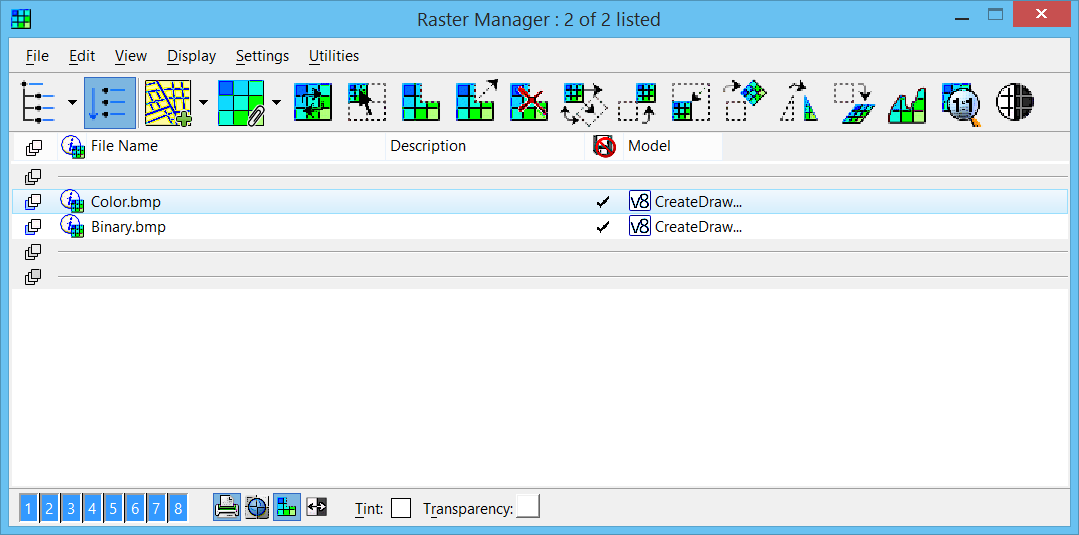
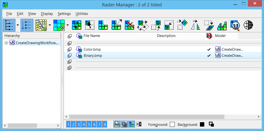
| Image list box |
Displays the File Name, Description, Read-Only status and Model of origin for all attached files. The Plane, Quick Info, Logical Name, Inherit GeoCS from Model, Draping, Security, Level, Display Priority, Geo Priority, Coordinate System, Display Gamma, Print Gamma, and Status fields can also be added to the menu bar by using the contextual (right-click) menu. When there is enough room, the name and path are shown. Columns can be dragged to change their order. The Plane column allows you to select which plane (Background, Design or Foreground) the rasters will display in. It is possible to change this information when using a multiple selection. When a multiple selection is used, the value of the first raster of the list is displayed in the edit dialog. By default this column is the first to the left and is turned ON. The image list panel is now divided in three sections, that is, one section per plane.
You can change the display sequence by dragging a file to a different position in the list. The display sequence of the raster images follow these rules:
- Raster images cannot be separated from the other images of the same design file.
- The display order of raster images that are attached through a model in reference is inherent to this model. When the referenced model is reloaded, the display order of the raster images will be updated.
- Only images from the active model can be moved with the "Bring Forward", "Send Backward", "Bring To Front" and "Send To Back" tools. Again, the images cannot be moved outside the range of the active model's image list. These tools will be grayed out if an image that is not in the active model is selected.
- If a model is self-referenced, changing the display order in the active model will also change the order of the images in the referenced model.
Resizing the dialog changes the size of this list box, letting you display as many image filenames as you require. When the number of files in the list exceeds the number of lines displayed, a scroll bar lets you scroll through the list.
One or more files can be selected from the list. When more than one file is selected, the information provided by the text fields, in the lower part of the dialog, applies to the first file of the list.
Double-clicking a filename opens the Properties dialog.
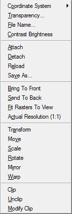
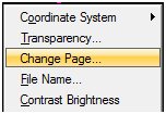
Right-clicking a highlighted file name opens the Raster contextual menu, which lets you perform many of the actions that are available in the Raster Manager dialog's File, Display and Utilities menus.
When right-clicking on multi-page rasters, the "Change Page" menu item is added to the contextual menu. Use to change the page of a multi-page raster attachment.
- Plane — Determines in which plane the raster will display. This is a per raster setting. It is also possible to display a raster as a vector element between vector elements , following the vectors display rules. Therefore, for each raster, users have the option of displaying it in the Background Plane, Design Plane or Foreground Plane. This generates three separate groups of rasters. The tools that modify the display order (bring to front, send to back, bring forward and send backward) are restricted to work inside a single group of the active design. Use this field to select in which plane (Background, Design or Foreground) the rasters are displayed. It is possible to change this information when using a multiple selection. When a multiple selection is used, the value of the first raster of the list is displayed in the edit dialog. By default this column is the first to the left and it is turned on.
- Quick Info — The Quick Info field displays an icon. When the cursor is placed over this field, a bubble appears with a short description of the raster. The following fields are displayed in the bubble: Full Path, Origin, Width, Height, Dimensions, Pixel Size, Scale Factor, Rotation and Affinity. This field is read-only.
- File Name — Displays the file name.
- Description — Displays a description of the raster.
- Logical Name — Displays the logical name of the raster.
- Read-Only — If on, the file is opened in a read-only mode and a check mark will appear in the Read-Only column.
- Inherit GeoCS from Model — If the attachment does not have a coordinate system, or if the coordinate system is deleted, the Inherit GeoCS from Model is set to on and cannot be changed. If a coordinate system is assigned to an attachment, the Inherit GeoCS from Model is set to OFF, but in this case, it can be turned on. If the Inherit GeoCS from Model is set to on, then the coordinate system assigned to the raster is not being used. In this case, the coordinate system displays in red in the Raster Manager dialog and (Unused) is written beside the coordinate system name in the Properties dialog. This toggle cannot be overridden.
- Draping — Indicates if Draping is enabled. When dcdrape.pal is added to a material table (.mat) which is attached to a DGN file, the draping is preserved and can be viewed directly in the application and rendered by the rendering engine when this field is toggled ON.
- Security — Attachments with this column checked are password protected and will not display. They will have the same behavior as attachments with the File not found status. Clicking the column opens a dialog to enter the password for the selected file(s). Multiple selections are supported to enter the password.
- Level — Shows which level the raster is on. Double-clicking the column displays a drop-down list box that lets you change the level for the selected raster.
- Display Priority — This column allows you to select the display priority. This column displays a valid priority value only if the Design Plane is selected for this raster. If another plane is selected, it is displayed --. A level value is automatically assigned to all newly attached raster. The raster is treated as a standard element and follows the rules that come with being on a level. This includes display, Freeze, Lock, Plot and Viewport Freeze operations. For 2D rasters, the display priority manages the display order of DGNs. For 3D rasters, the Z elevation manages the display order of DGNs.
- Geo Priority — The Geo Priority field displays the method used to geographically position the image. The available methods are Attachment, Raster Header, Sister File and From Preferences. The image may have native geographic metadata stored in the image itself (raster header) or in a companion file (sister file or world file). When no native methods are present, the image is geographically positioned by the user and the metadata is stored in the design file. This method is called "attachment". The geographic metadata is always preserved and updated in the Attachment. When specified otherwise, the alternate location is updated as well as the attachment. Hence, the attachment is constantly updated to reflect the current geographic information of the image. In cases where the image has native geographic metadata, once attached to a design file, it is sometimes useful to specify which metadata storage to use such as Raster Header, Attachment or Sister File. The Raster Manager preferences allow some flexibility to that effect. The Geo Priority column displays the method used to position the image and, upon reopening the design file, will display in RED if the previous method cannot be used. For example, you may want to attach an image using a sister file, but once attached you want the geographic metadata to be read from the attachment. You would then set the preferences to prioritize native geographic metadata and would change the Geo Priority to attachment. The Geo Priority is also very useful to warn about potential data loss. For example, if the preferences are set to always read the geographic metadata from a sister file but the sister file is not present, Raster Manager will use the Attachment information and will highlight the column in red showing an error has occurred. The status column will also display the alternate method used to geographically position the image, in this case "attachment".The Geo Priority feature allows each image to have its own Geo Priority. In versions before 2004 Edition, the same Geo Priority was forced to all images. When an older file version is opened and where no Geo Priority was previously set, the Geo Priority will be set to From Preferences. This indicates that the Raster Manager preferences will dictate how Georeference for this image is handled. If the Raster Manager Preferences are set identically to the previous version, the image will display and position identically. If the Preferences are set differently, it is possible that the image displays and positions differently. If this is the case, adjust the Geo Priority before saving and closing the design file and change the Raster Manager Preferences accordingly. To change the Geo Priority, simply click in the Geo Priority column to open the Geo Priority dialog. You can then change the selection.
- Coordinate System — This column displays the Coordinate System, for an image, that will be used for a transformation operation such as On-the-Fly or Fence Transform. The Coordinate Systems assigned to an image can be issued from the Design File or the Image Header. If the image does not have an associated Coordinate System, the field displays Inherited from DGN. This indicates that when a transformation operation will be executed, the image will be assigned to the same Coordinate System assigned to the design file it is attached to. When the image has an associated Coordinate System, the column displays an abbreviation of the Coordinate System name. To read detailed information about the Coordinate System, simply move the cursor over the column to display a tooltip information box. To open the Coordinate System dialog, simply double-click on the column. Unless Bentley Descartes is loaded, this dialog displays in read-only mode and all the fields are grayed out.
- Model — The Model field is used to display the origin (design name and model name) of the raster reference.
- Display Gamma — Sets the display gamma correction value. The base value is 1.0. A value lower than 1.0 creates a darker image, a value higher than 1.0 creates a lighter image.
- Print Gamma — Sets the gamma correction value for the printer.
- Status — The Status field displays the reference's status (Loaded, Referenced, Self-Referenced or Raster Not Found). When a file is not found, its name is displayed in red, with the message "Raster not found" appearing in the Status field.
IMGMANAGER
IMAGE SELECT
[
viewnumber
]
[
filename
]
IMGMANAGER
IMAGE UNSELECT
[
viewnumber
]
[
filename
]
|
| View buttons |
Numbered push buttons let you define in which view(s) to display the raster reference(s). |
| Print icon |
If on, permits the raster image to be printed. |
| Transparent icon |
If on, the selected Transparent Color (for color images), or Background Color (for monochrome images), becomes transparent, allowing DGN elements or other images to show through the image. |
| Clip icon |
For raster references that have been clipped only. If on, the raster reference displays with clipping enabled. If off, then the clipping polygon is ignored and the image displays in full. |
| Invert icon |
If on, the colors for the raster image are inverted. This is similar to making a negative of a photograph. |
| Tint icon |
For colored images, the Tint Color setting is used to add a tint to the colors in the raster image.
RASTER
FOREGROUND
COLOR
RASTER
TINT
COLOR
RASTER
TINT
RGB
|
| Transparency icon |
For colored images, the Transparency setting is used to set a transparent color for the raster reference. The selected color in the raster image then becomes transparent, when the Transparent setting is enabled. For monochrome images, the Background Color setting is used to set the background color of the raster file.
The chosen transparency color also is used as a fill color when clipping raster images.
RASTER
BACKGROUND
COLOR
RASTER
TRANSPARENT
COLOR
RASTER
TRANSPARENT
RGB
|
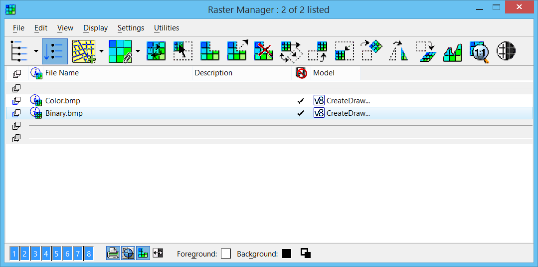
| Swap Background icon |
For monochrome images, the Foreground Color setting controls the color of foreground items and the Background Color setting is used to set the background color of the raster file. Use this tool to invert the Foreground and Background colors. The chosen background color is used as a fill color when clipping raster images.
|
| File > New > WMS |
Opens the
WMS Map Editor dialog
, which lets you create a new map definition file. |
| File > New > Image Server |
Opens the Image Server Settings dialog, which lets you define the new image server settings. |
| File > Attach > Raster |
Performs the same function as the
Attach
tool. Opens the
Attach Raster Reference dialog
, which lets you attach raster image files to the active DGN file.
RASTER
ATTACH
FIXED
RASTER
ATTACH
INTERACTIVE
IMGMANAGER
FILE
OPEN
RASTER
ATTACH
|
| File > Attach > WMS |
Opens the
Attach Raster Reference dialog
, which lets you attach WMS files to the active DGN file. The WMS is always attached as read-only and cannot be placed interactively. The Attachment Properties dialog always displays. WMS Geo Priority is always set to "Raster Header". |
| File > Attach > From Image Server |
Opens the
Attach Raster Reference dialog
, which lets you attach raster files from the available image servers. |
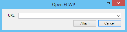
| File > Attach > ECWP Image Server |
Opens the Open ECWP dialog, which lets you attach ECW files from an ECWP Image Server to the active DGN file. The ECW is always attached as read-only and cannot be placed interactively. The Attachment Properties dialog always displays. The Open ECWP dialog keeps the history of the URL used to attach ECW files from ECWP Image servers.
|
| File > Attach > Bing Maps |
Opens the Raster Attachment Options dialog which is used to attach a layer from Bing Maps as a raster in the Raster Manager. |
| File > Detach |
Detaches the selected raster reference(s).
RASTER
DETACH
IMGMANAGER
FILE
CLOSE
|
| File > Detach All |
Detaches all raster image files.
RASTER
DETACH ALL
IMGMANAGER
FILE
CLOSEALL
|
| File > Reload |
Refreshes the selected raster file(s), using the current data of the file(s).
RASTER
RELOAD
|
| File > Save As… |
Opens the Save Raster As dialog, which lets you save the currently selected image in another format. This item is disabled if more than one raster image file is selected.
IMGMANAGER
FILE
SAVEAS
RASTER
SAVEALL
RASTER
SAVESELECTED
|
| File > Import > Raster Save Set |
Opens the Import Bentley I/RAS B Raster Save Set dialog, an standard file selection dialog which is used to select a Raster Save Set to import. By default, Files of Type is set to Raster Save Set files (*.rst). The controls in this dialog are analogous to those in the Open dialog. |
| File > Batch Convert |
Opens the Raster Convert dialog, which lets you convert one or more raster files to a new format.
IMGMANAGER
FILE
BATCHCONVER
[
[filename]
]
|
| Edit > Transform |
Provides access to the Transform Raster tool, which lets you modify the selected raster reference. |
| Edit > Move |
Performs the same functions as the raster
Move
tool. Lets you move an image to a new location.
RASTER
MOVE
|
| Edit > Scale |
Performs the same functions as the raster
Scale
tool. Lets you change the proportionate dimensions of an image.
RASTER
SCALE
[
ACTIVE |
3POINTS |
PROPORTIONAL |
PROPORTIONAL ON |
PROPORTIONAL OFF |
PROPORTIONAL TOGGLE
]
|
| Edit > Rotate |
Performs the same functions as the raster
Rotate
tool. Lets you rotate an image.
RASTER
ROTATE
RASTER
ROTATE
[
ACTIVE |
2POINTS |
3POINTS
]
|
| Edit > Mirror |
Performs the same functions as the raster
Mirror
tool. Lets you mirror the selected raster image file horizontally, vertically, or diagonally. Additionally, you can specify the location of the axis about which the image is mirrored.
RASTER
MIRROR
HORIZONTAL
RASTER
MIRROR
VERTICAL
|
| Edit > Warp |
Performs the same functions as the raster
Warp
tool. Lets you adjust the size and shape of a raster image with a combination of move, scale, rotate, and skew options.
RASTER
WARP
AFFINE
RASTER
WARP
HELMERT
RASTER
WARP
ALIGN
RASTER
WARP
SIMILITUDE
|
| Edit > Clip |
Performs the same functions as the raster
Clip
tool. Lets you crop a raster image, or define a masked area.
RASTER
CLIP
BOUNDARY
RASTER
CLIP
MASK
|
| Edit > Unclip |
Performs the same functions as the raster
Unclip
tool. Lets you remove one or more clipping polygons from a raster image. |
| Edit > Modify Clip |
Performs the same functions as the
Modify Clip
tool. Lets you modify a clipping polygon graphically.
RASTER
TOOLMODIFY
|
| View > Show Hierarchy |
If on, the tree view is visible. |
| View > Flat Mode |
The rasters of all sub-folder will be listed. |
| View > Background Plane |
If on, the image(s) in the background plane will be displayed in the list box. |
| View > Design Plane |
If on, the image(s) in the design plane will be displayed in the list box. |
| View > Foreground Plane |
If on, the image(s) in the foreground plane will be displayed in the list box. |
| Display > Bring to Front |
Performs the same function as the
Bring to Front
tool, with Action set to To Front. Brings the selected image(s) to the front of the display stack.
IMGMANAGER
DISPLAY
FRONT
[
ViewName
]
|
| Display > Send to Back |
Performs the same function as the
Send to Back
tool, with Action set to To Back. Sends the selected image(s) to the back of the display stack.
IMGMANAGER
DISPLAY
BACK
|
| Display > Bring Forward |
Performs the same function as the
Bring to Front
tool, with Action set to One Step. Brings the selected image one step forward (up) in the display stack. |
| Display > Send Backward |
Performs the same function as the
Send to Back
tool, with Action set to One Step. Sends the selected image one step backward (down) in the display stack. |
| Display > Fit Rasters to View |
Performs the same function as the
Fit to View
tool, with Mode set to Selected Rasters. Fits the selected images to a view, which is defined with a data point.
IMGMANAGER
DISPLAY
FIT
RASTER
FIT
|
| Display > Fit All Rasters to View |
Performs the same function as the
Fit to View
tool, with Mode set to All Rasters. Fits all images to a view, which is defined with a data point.
IMGMANAGER
DISPLAY
FITALL
RASTER
FITALL
|
| Display > Actual Resolution (1:1) |
Displays the selected image at its resolution scale (1:1). A data point defines the center point of the view. (When only one image is opened, it is selected). Performs a similar function as the
Actual Resolution 1:1
tool, which lets you select interactively the raster image to fit.
IMGMANAGER
DISPLAY
1FOR1
|
| Display > Enhance Binary |
Turn on to enhance the display of binary raster attachments when the view is zoomed out and causes loss of detail in display. |
| Display > Annotations > Explore |
Display the content of annotations. All the annotation bullets are displayed even if the "Show" toggle is off. Move the cursor of the Explore Annotation tool over the selection region of an annotation, the selection region is highlighted. The annotation content is only visible when a data point is entered into the annotation selection region.
|
| Display > Annotations > Show |
Turn on or off the display of annotations bullets. |
| Settings > Update Sequence |
Opens the
Update Sequence dialog
, which lets you change the display order whenever a view update is involved. |
| Settings > Cache Manager |
Opens the Cache Manager dialog, which is used to manage raster image cache files generated on your hard disk. |
| Settings > Image Servers |
Opens the Image Server Settings dialog , which lets you create new server configuration files or modify existing server configuration files. The Image Server utility requires that a Bentley publishing server be installed.
IMGMANAGER
DLGSERVERSETTING
OPEN
|
| Settings > Annotations |
Opens the Annotations Settings dialog which lets you set the color to use and the percentage of transparency for the dynamic highlight of annotations. Note: The current version supports only annotations that display text. If you move over an unsupported annotation, it will be highlighted but a message will notify you that this type of annotation is not supported.
|
| Utilities > Edit WMS |
Opens the WMS Map Editor dialog, which lets you create or edit a map definition file. |
| Utilities > Layers |
Opens the Layer Display dialog, which lets you access the available layers. |
| Utilities > Coordinate System > Select From Library |
Allows you to select a coordinate system from the predefined library supplied with the product. |
| Utilities > Coordinate System > Delete |
Deletes the specified coordinate system. |
| Utilities > Transparency |
Opens the Transparency dialog, which allows you to determine the transparency settings for the selected raster. |
| Utilities > File Name |
Opens the File Name dialog allowing to enter or select a name for the selected raster. |
| Utilities > Contrast Brightness |
Used to adjust the contrast and brightness for the display of raster image files attached to the design file. |
 Used to control the display of one or more raster images in a DGN file view.