P. To add a plan drawing
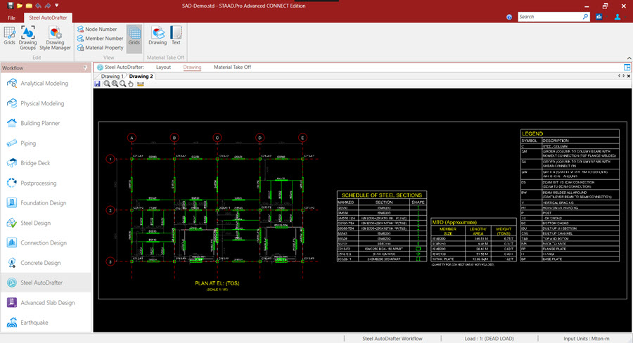
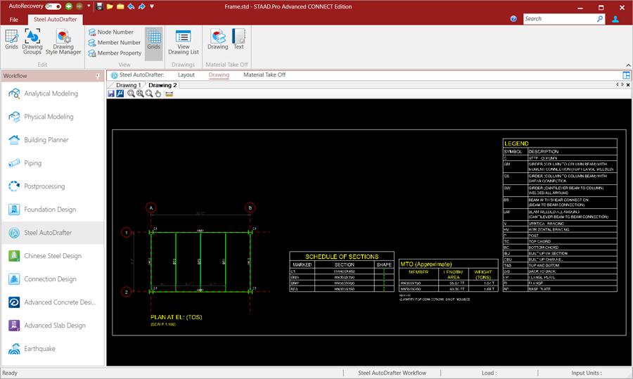
To create a plan drawing of members at the same elevation, use the following procedure.
-
Right-click and then select
Draw Plan @Y =
elevation
from the
pop-up menu.
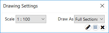
The Drawing Settings dialog opens.
-
Either:
- click
 Draw to generate the drawing
- click
 Add to Drawing List to add this drawing to
the Drawing List tab
Add to Drawing List to add this drawing to
the Drawing List tab
- click
The top of steel (TOS) for beams is adjusted as Y coordinate of the floor. Accordingly the center line of the beam is shifted down by half the beam depth.

Tip: Alternatively, you can use the
options in the
Drawing List tab to select
Plan from the
Type drop-down list to create a plan drawing at
a selected
Location.
If you selected to add this drawing to the
drawing list, then click the
Draw tool below the list on the
Drawing List tab to generate all of your
drawings.