EX. To designate the wall-slab connection
To mesh the wall such that it is compatible with the slab mesh, use the following procedure.
-
On the
View ribbon tab, select the
Display Whole Structure tool in the
Tools group.

The standard view is restored, displaying the hidden portions to the view. - Optional:
On the
Select ribbon tab, select the
All tool in the
Beams group.

Tip: It is not necessary to select the members in order to perform the next steps. However, this can server as an easy way to identify the edges of the slab-wall interface when selecting the vertices. -
On the
Geometry ribbon tab, select the
Wall/Slab Connection tool in the
Structure group.

The mouse pointer changes to the add surface cursor .
. -
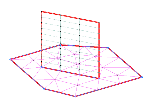
Starting with the two nodes at the base, select the four corner
nodes of the wall in a clockwise order, clicking on the first selected node a
second time to complete the boundary definition.
 The Division along wall dialog opens.
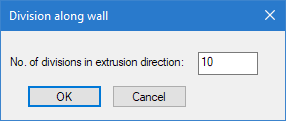 Note: As the divisions along the base of the wall must be compatible with the slab density line, this value will control the meshing along the sides.