G.4.2 Local Coordinate System
A local coordinate system is associated with each member. Each axis of the local orthogonal coordinate system is also based on the right hand rule.
The following figures show a beam member with start joint 'i' and end joint 'j'. The positive direction of the local x-axis is determined by joining 'i' to 'j' and projecting it in the same direction. The right hand rule may be applied to obtain the positive directions of the local y and z axes. The local y and z-axes coincide with the axes of the two principal moments of inertia. Note that the local coordinate system is always rectangular.
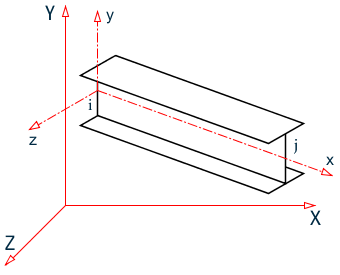
When Global-Y is Vertical
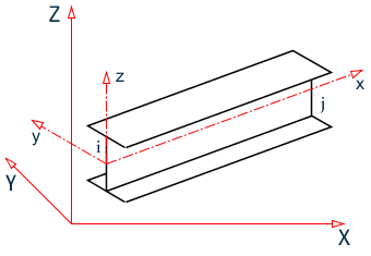
When Global-Z is Vertical (that is, SET Z UP is specified)
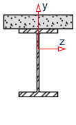
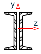
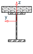
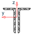
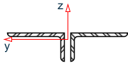
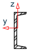
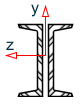
A wide range of cross-sectional shapes may be specified for analysis. These include rolled steel shapes, user-specified prismatic shapes etc.. The following table shows local axis system(s) for these shapes.

Wide Flange - ST |

Wide Flange - TB |
Wide Flange - CM |
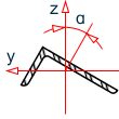
Angle - ST |
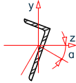
Angle - RA |
Angle - LD (Long legs back-to-back) |
Angle - SD (Short legs back-to-back) |

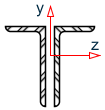
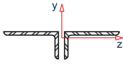
Wide Flange - T |
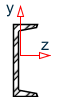
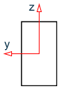
Channel - ST |
Channel - D |
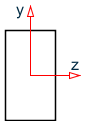
Prismatic |
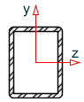
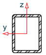
Tube - ST |
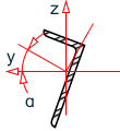
Local axis system for various cross sections when global Y axis is vertical
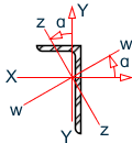
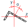
Labels for the local axes of a single angle as defined in AISC publications.

Wide Flange - ST |

Wide Flange - TB |
Wide Flange - CM |
Angle - LD |
Angle - SD |
Channel - ST |

Wide Flange - T |
Channel - D |
Prismatic |
Tube - ST |
Angle - ST |
Angle - RA |