G.5.1 Plate and Shell Elements
The plate (or shell) finite element is based on the hybrid element formulation. The element can be 3-noded (triangular) or 4-noded (quadrilateral). If all the four nodes of a quadrilateral element do not lie on one plane, it is advisable to model them as triangular elements. The thickness of the element may be different from one node to another.
"Surface structures" such as walls, slabs, plates and shells may be modeled using finite elements. For convenience in generation of a finer mesh of plate/shell elements within a large area, a MESH GENERATION facility is available.See TR.14 Plate Element Mesh Generation for details.
You may also use the element for PLANE STRESS action only (i.e., membrane/in-plane stiffness only). The ELEMENT PLANE STRESS command should be used for this purpose.
Geometry Modeling Considerations
-
The program automatically generates a fictitious, center node "0" (see the following figure) at the element center.
Fictitious center node (in the case of triangular elements, a fourth node; in the case of rectangular elements, a fifth node)
-
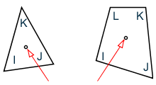
While assigning nodes to an element in the input data, it is essential that the nodes be specified either clockwise or counter clockwise (see the following figure). For better efficiency, similar elements should be numbered sequentially.

Examples of correct and incorrect numbering sequences
-
Element aspect ratio should not be excessive. They should be on the order of 1:1, and preferably less than 4:1.
-
Individual elements should not be distorted. Angles between two adjacent element sides should not be much larger than 90 and never larger than 180.

Load Specification for Plate Elements
- Joint loads at element nodes in global directions.
- Concentrated loads at any user specified point within the element in global or local directions.
- Uniform pressure on element surface in global or local directions.
- Partial uniform pressure on user specified portion of element surface in global or local directions.
- Linearly varying pressure on element surface in local directions.
- Temperature load due to uniform increase or decrease of temperature.
- Temperature load due to difference in temperature between top and bottom surfaces of the element.
Theoretical Basis

Assumed stress distribution
The incomplete quadratic assumed stress distribution:
- a1 through a10 = constants of stress polynomials
The following quadratic stress distribution is assumed for plate bending action:
Quadratic stress distribution assumed for bending
The incomplete quadratic assumed stress distribution:
- a1 through a13 = constants of stress polynomials
The distinguishing features of this finite element are:
-
Displacement compatibility between the plane stress component of one element and the plate bending component of an adjacent element which is at an angle to the first (see the following figure) is achieved by the elements. This compatibility requirement is usually ignored in most flat shell/plate elements.

Adjacent elements at some angle
-
The out of plane rotational stiffness from the plane stress portion of each element is usefully incorporated and not treated as a dummy as is usually done in most commonly available commercial software.
-
Despite the incorporation of the rotational stiffness mentioned previously, the elements satisfy the patch test absolutely.
-
These elements are available as triangles and quadrilaterals, with corner nodes only, with each node having six degrees of freedom.
-
These elements are the simplest forms of flat shell/plate elements possible with corner nodes only and six degrees of freedom per node. Yet solutions to sample problems converge rapidly to accurate answers even with a large mesh size.
-
These elements may be connected to plane/space frame members with full displacement compatibility. No additional restraints/releases are required.
-
Out of plane shear strain energy is incorporated in the formulation of the plate bending component. As a result, the elements respond to Poisson boundary conditions which are considered to be more accurate than the customary Kirchoff boundary conditions.
-
The plate bending portion can handle thick and thin plates, thus extending the usefulness of the plate elements into a multiplicity of problems. In addition, the thickness of the plate is taken into consideration in calculating the out of plane shear.
-
The plane stress triangle behaves almost on par with the well known linear stress triangle. The triangles of most similar flat shell elements incorporate the constant stress triangle which has very slow rates of convergence. Thus the triangular shell element is very useful in problems with double curvature where the quadrilateral element may not be suitable.
-
Stress retrieval at nodes and at any point within the element.
Plate Element Local Coordinate System
-
The vector pointing from I to J is defined to be parallel to the local x- axis.
-
For triangles: the cross-product of vectors IJ and JK defines a vector parallel to the local z-axis, i.e., z = IJ x JK.
For quads: the cross-product of vectors IJ and JL defines a vector parallel to the local z-axis, i.e., z = IJ x JL.
-
The cross-product of vectors z and x defines a vector parallel to the local y- axis, i.e., y = z x x.
-
The origin of the axes is at the center (average) of the four joint locations (three joint locations for a triangle).

Element origin
Output of Plate Element Stresses and Moments
ELEMENT stress and moment output is available at the following locations:
- Center point of the element.
- All corner nodes of the element.
- At any user specified point within the element.
Following are the items included in the ELEMENT STRESS output.
| Title | Description |
|---|---|
| SQX, SQY | Shear stresses (Force/ unit length/ thickness) |
| SX, SY | Membrane stresses (Force/unit length/ thickness) |
| SXY | Inplane Shear Stress (Force/unit length/ thickness) |
| MX, MY, MXY |
Moments per unit width (Force x Length/length) (For Mx, the unit width is a unit distance parallel to the local Y axis. For My, the unit width is a unit distance parallel to the local X axis. Mx and My cause bending, while Mxy causes the element to twist out-of-plane.) |
| SMAX, SMIN | Principal stresses in the plane of the element (Force/unit area). The 3rd principal stress is 0.0 |
| TMAX | Maximum 2D shear stress in the plane of the element (Force/unit area) |
| VONT, VONB |
3D Von Mises stress at the top and bottom surfaces, where: VM = 0.707[(SMAX - SMIN)2 + SMAX2 + SMIN2]1/2 |
| TRESCAT, TRESCAB | Tresca stress, where TRESCA = MAX[ |(Smax-Smin)| , |(Smax)| , |(Smin)| ] |
Notes
-
All element stress output is in the local coordinate system. The direction and sense of the element stresses are explained in the following section.
-
To obtain element stresses at a specified point within the element, you must provide the location (local X, local Y) in the coordinate system for the element. The origin of the local coordinate system coincides with the center of the element.
-
The 2 nonzero Principal stresses at the surface (SMAX & SMIN), the maximum 2D shear stress (TMAX), the 2D orientation of the principal plane (ANGLE), the 3D Von Mises stress (VONT & VONB), and the 3D Tresca stress (TRESCAT & TRESCAB) are also printed for the top and bottom surfaces of the elements. The top and the bottom surfaces are determined on the basis of the direction of the local z-axis.
-
The third principal stress is assumed to be zero at the surfaces for use in Von Mises and Tresca stress calculations. However, the TMAX and ANGLE are based only on the 2D inplane stresses (SMAX & SMIN) at the surface. The 3D maximum shear stress at the surface is not calculated but would be equal to the 3D Tresca stress divided by 2.0.
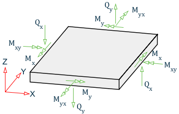
Sign Convention of Plate Element Stresses and Moments
See TR.42 Print Specifications for definitions of the nomenclature used in the following figures.

Sign conventions for plate stresses and moments

Sign convention for plate bending
Mx is the Bending Moment on the local x face and the local x-face is the face perpendicular to the local x-axis.
My is the Bending Moment on the local y face and the local y-face is the face perpendicular to the local y-axis.

Stress caused by Mx

Stress caused by My

Torsion

Membrane stress Sx and Sy
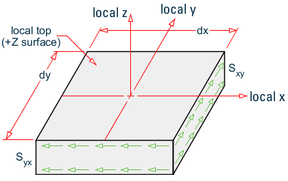
In-plane shear stresses Sxy and Syx

Out-of-plane shear stresses SQX and SQY
Members, plate elements, solid elements and surface elements can all be part of a single STAAD model. The MEMBER INCIDENCES input must precede the INCIDENCE input for plates, solids or surfaces. All INCIDENCEs must precede other input such as properties, constants, releases, loads, etc. The selfweight of the finite elements is converted to joint loads at the connected nodes and is not used as an element pressure load.
Plate Element Numbering
Therefore, to save some computing time, similar elements should be numbered sequentially. The following figure shows examples of efficient and non-efficient element numbering.
However, you have to decide between adopting a numbering system which reduces the computation time versus a numbering system which increases the ease of defining the structure geometry.
