Initial Stress/Strain (Temperature, etc.)
Primary Stress in Point – load type TSTR0
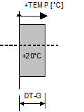
Temperature load – load type T
The variation of the temperature load in longitudinal direction (over the element length) is always assumed constant over the whole element length. A suitable subdivision of the structure into small elements with constant temperature must be made to simulate essentially varying temperatures in beam longitudinal direction.
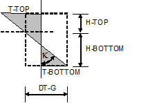
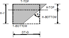
The temperature gradients (TGy, TGz), and consequently the related strain gradients (κy) and (κz), are specified by value pairs of temperature difference and related length or width (DT-Y, H-Y and DT-Z, H-Z respectively).
| Setting | Description |
|---|---|
| DT-Y, H-Y | Temperature difference DT-Y and related height H-Y, describing the temperature gradient TGy= DT-Y/H-Y in the local y-direction, producing only bending strains in the X-Y plane. |
| DT-Z, H-Z | Temperature difference DT-Z and related height H-Z, describing the temperature gradient TGz= DT-Z/H-Z in the local z-direction, producing only bending strains in the X-Z plane. |
Some design codes require a non-linear variation of the temperature over the cross-section to be investigated (e.g. AASHTO). RM Bridge offers a possibility to take this demand into account by defining the temperature distribution in the cross-section very detailed and selecting the function TempVar to calculate the appropriate integrals characterizing the equivalent uniform temperature change and the gradients. This function is described in detail in section TempVar.
Cable shortening defined by an equivalent force – load type FX0
| Load Type | Description |
|---|---|
| FX0 | Equivalent normal force in the element; a stress-free element length differing from the system length is assigned to the element by specifying the equivalent normal force Fx required for yielding this length difference. The effect of this load type is identical to LX0. At first, the stress-free length LX0 = LX / (1+Fx/(E×A) is internally computed by using the specified normal force Fx. Then the program proceeds in the same manner than for load type LX0. |
Secondary component – bending part – load type TB
| Load Type | Description |
|---|---|
| TB | This and the ensuing 3 Load Types define strain states linearly distributed over the element length. These strain states are defined by specifying equivalent internal force states. The total strain state is separated in a bending part (TB) and a shear part (TS). A "primary" part can in addition be specified (TB0, TS0). |
The input parameters related to the bending part are the normal force and the 2 bending moments at the start and end points of the elements. The represent the longitudinal strain εs in the center of gravity and the bending strains χy and χZ (gradients of longitudinal strains in y and z directions).
The shear part is specified by the torsional moment and the 2 shear forces, representing the respective shear strain components.
Both, bending and shear part may be separated in a "secondary part", which causes reactions of the structural system, and a "primary part", which characterizes the non-linearity of the strain distribution over the cross-section. The related internal forces (stress integrals over the cross-section) are internally in equilibrium on the cross-section level.
The load type TB describes the secondary part of the bending strain. Loading definitions of this type with the respective parameters are automatically generated in the schedule action TempVar in case of calculating the effects of a non-linear temperature loading. They are written into the corresponding load sets and can be viewed in the GUI after this schedule action has been successfully performed.
Using the load types TB, TB0, TS, TS0 for directly defining equivalent strain states requires a deeper insight and is not recommended in practical applications.
Secondary component – shear part – load type TS
| Load Type | Description |
|---|---|
| TS | Secondary shear-part of the strain state; this part occurs theoretically in the case of temperature loading varying in the longitudinal direction. For modeling the effects of non-linear temperature in TempVar it is seldom generated (only if the cross-sections at the start and end of the element are different). Shear forces only arise due to equilibrium conditions if the end moments related to the temperature gradient are different on both ends of the element. |
Primary component – bending part – load type TB0
| Load Type | Description |
|---|---|
| TB | The primary part is also defined in terms of internal forces, although it characterises an internal equilibrium state. The fictitious internal force characterising this state is defined to be the force producing the correct stress in 2 points of the cross-section (the upper and lower edge). This part is generated in the case of non-linear temperature calculation, if the option Include Primary TempVar effects has been selected in the Recalc pad. |
Stress-free element lenght - load type LX0
Both load types LX0 and FX0 correspond physically to the installation process of a pre-stressed cable stressed in a pre-stressing bed (not against the system). (The load type FCAB simulates stressing against the system). This pre-stressed element is installed in the actual system. The actual distance between the connection points characterises the length in the fully (with Fx) pre-stressed state. LX0 is the length arising in the case that the connection to the system is dropped. The calculation process simulates removing the pre-stressing bed. The pre-stressing forces are then acting on the system at both connection points. The system will give way and the resulting force in the cable will be (more or less, depending on the system stiffness) smaller than the specified fixed end value Fx.