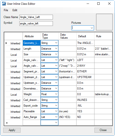
User Inline Class Editor
Both the New and Edit commands in the User Inline List opens the User Inline Class Editor. New opens an empty editor, while Edit opens the editor for the selected inline. This dialog is where inlines are named, geometry is described, attributes are defined, and attribute rules are created.
As with many other PlantWise dialogs, the User Inline Class Editor has the following controls:
| Setting | Description |
|---|---|
| File menu |
You can Save Library and Close the dialog from this menu. It is important to save the Equipment Library, as changes to it are not be saved with a model. Also, closing the dialog with un-Accepted changes loses those changes. |
| Highlighted sections | A right mouse click in the highlighted sections opens up specialized pop up menus. Those menus are covered with the specific section of the dialog. |
| Accept | Changes to a UDI are not written to the Equipment Library until this button has be clicked. The button is disabled until a change has been made. |
| Close | Closes the dialog. Closing the dialog with un-Accepted changes loses those changes. |
| Class Name | The Class Name field is
where the UDI name is entered. This name ise used to store the class in the
User Equipment library and cannot contain spaces ( ), colons (:), or commas
(,).
The Class Name is a list box that allows you to view all of the defined UDIs without going back to the Inline Class List. If you change the current UDI in the editor, all changes made to the previous inline since the last Accept are lost. |
| For new classes |
|
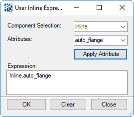
| Geometry Description | This is where the geometric description of the Inline is defined using the same language as for Defining Equipment Geometry rules. The only components that can be referred to in the geometry description are the inline (inline.<attribute>) and the pipeline (pipeline.<attribute>). See "User Inline Attributes " for a full list of user inline attributes. |
| Picture File Reference | When checked, it means there is an image file for this inline you can use as reference. The file name is entered in the Filename filed that appears when the checkbox is checked. The picture files must be in either the pictures folder of the PlantWise installation folder or the pictures folder under the current project folder. File names are saved with the UDI so that it can be viewed in future sessions |
| Show | Opens a dialog that shows the Picture File Reference. |
| Attributes list | UDIs have seven default attributes that must be
defined and may have as many user defined attributes as necessary.
All attributes are listed in the Attributes List
box. There are five columns in the list box that display the following
information:
|

Attributes list box
Selecting an attribute displays the current values in the fields below the Attributes List box for editing. A right mouse click in the Attributes List box opens a Swap menu.
| Attribute name | Description |
|---|---|
| User_class_name | The name normally displayed to you. It may contain spaces and/or dashes. |
| Segment_perference | Whether the UDI prefers to be placed on a Horizontal, a Vertical, or Either orientated pipe run. |
| Upstream_downstream_attraction | Whether the UDI should be placed relative to its Upstream or Downstream neighbor. |
| Downstream_spacing | Distance in the downstream direction this UDI must be from the next inline component. |
| Upstream_spacing | Distance in the upstream direction this UDI must be from the next inline component. |
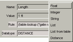
| Length | How much length of pipe is removed for the placement of the inline. This value cannot be zero, but it can be very small. |
| Cad_drawing_level | The CAD level on which the UDI is drawn. |
| Placeable | If the inline is a placeable or slideable component (see Manipulating Inlines for more on placeable and slideable inline components). |
| Export_code | The string identifier for this class of user inline for pipeline export reports. |
Angled Valves
PlantWise also has the capability to place a user defined inline at a horizontal elbow.
| Attribute name | Description |
|---|---|
| Angle_valve_dir | The direction (Left or Right) of the angle of the component along the pipeline’s flow direction. |
| Angle_valve_type | If there is a tee directly upstream of the component, it will place next to the valve if the angle_valve_type is set to 3-way. If an upstream tee does not need to be attracted to the valve, then the angle_valve_type should be set to 2-way. |