| On element surface
|
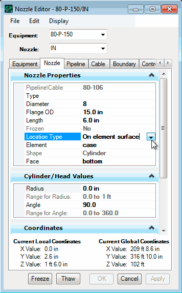
For placing of nozzles on an element surface,
you specify the element, face of the element, and placement values for the
nozzle.
Element indicates which
element of the equipment the nozzle has been placed on.
Note: Nozzles can
only be placed on elements that are box, cylinder, or elliptical head
primitives.
Face indicates which face of the
element the nozzle is on.
The next two fields depend on face type:
- For rectangular
faces, you enter the
U-Distance and the
V-Distance.
- For circular faces,
you enter the
Radius and
Angle.
- For body faces of
cylinders, you enter
Distance and
Angle.
From the
Orientation Vector fields, you can change
the direction the nozzle points to. You are reminded that the
Z Component vector is the outward normal
to the surface of the face the nozzle is placed on.
The
Current Global Coordinates lists the
location of the nozzle (center of nozzle) with respect to the project’s global
coordinates. This section of the dialog does not change with Location Type.
|
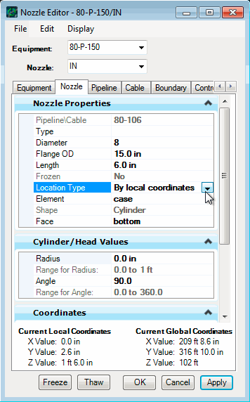
| By local coordinates
|
Local coordinates allow you to
place nozzles in x, y, and z with the placement point of the equipment instance
acting as the origin of the coordinate system. Changing the Orientation vector
of the nozzle is done with respect to the orientation of the equipment.
By local
coordinates
|
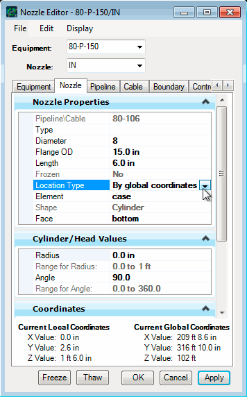
| By global coordinates
|
Global coordinates allow you to
place nozzles in absolute x, y, and z. The Orientation vector of the nozzle is
with respect to the global axes of the project.
By global
coordinates
|