CAD Menu
The CAD menu contains commands to control the display of components.

| Setting | Description |
|---|---|
| Redraw | Synchronizes the knowledge base portion of PlantWise to CAD communication. If changes have been made to the design file without using PlantWise commands, Redraw corrects the drawing to match the PlantWise database. |
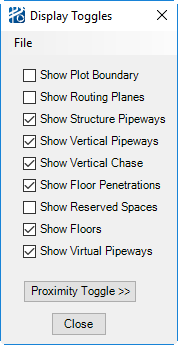
| Display Toggles... | Opens the Display Toggles dialog. From
here you can turn on and off the display of the model components that are not
generally displayed.
|
| Pipeline Display Preferences... | Opens the Pipeline Display Properties dialog. |
| All Groups... | Opens the All Named Groups dialog. (See Group Edits for details on PlantWise groups). |
| Highlight Set | Opens the Highlight Component Set dialog so that you can generate a graphical report. |
| UnHighlight All | Un-Highlights all Highlighted elements of the model returning them to their original CAD Levels. |
| PlantDrafter... | Opens the Drawing List dialog. |