Router Toolbox
The Router Toolbox is a floating menu palette that provides rapid access to frequently used commands.

CAD Router Toolbox (from left to right: Route, Manual Route, Unroute, Connect Pipe, 3D Bends, 5D Bends, 7D Bends, 10D Bends, Modify, Slide, Support).
| Setting | Description |
|---|---|
| R – Route | Opens the Router Control Dialog for automatic routing and rerouting of pipelines. Reroute pipelines with the Route command any time a pipeline has been removed due to changed data |
| M – Manual Route | Allows you to draw a Smart Line in CAD and assign a pipeline route to it. After drawing the line and clicking the Manual Route button on the Router Toolbox, you are prompted twice: first, for the line to assign to the path; and second, if the line is a center of pipe or bottom of pipe representation. |
| U – Unroute | Removes all pipe routes, after prompting you for confirmation. |
| C – Connect Pipe | Allows you to specify connectivity by selecting
PlantWise components. After
clicking this button, you are prompted to select and accept the origin. Then
prompted to select and accept the terminus.
Valid components for the origin/terminus selection are equipment, nozzles, boundaries, pipes, or pipeway components. After the origin and terminus are selected and accepted, a dialog opens, that allows you to select the pipe to be connected. After you select a pipe and Accept the selection, the Connectivity Editor opens with the components selected used for the input fields. You simply need to accept the Connectivity Editor dialog, and the selected pipe then connects to the components selected. |
| 1D 1.5 3D, 5D, 7D, and 10D | Allows you to change the bending radius of any pipe. After clicking the icon, MicroStation prompts to select a pipe and if the selection is accepted the pipe uses either 1, 1.5, 3, 5, 7, or 10 times the pipe’s nominal diameter as the bending radios for all bends (elbows) on the pipe’s route. |
| Modify | Provides interactive pipe route and inline placement changes by opening either the Segment/Point Manipulator or one of the inline editors (see "Inline Component Editors"). |
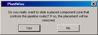
| Slide | Moves inline components along the path of the pipeline. If the component is placeable, you are prompted with the message (see "Manipulating Inlines" for more on slideable and placeable components). |
| Support | Opens the Pipe Support Editor to interactively place pipe supports under already-routed pipes as described under "The Pipe Support Editor". Before creating a new support, you need to define which pipes are to be supported by drawing CAD fence around them at the preferred location for the support. The dialog allows editing and deleting of supports. |