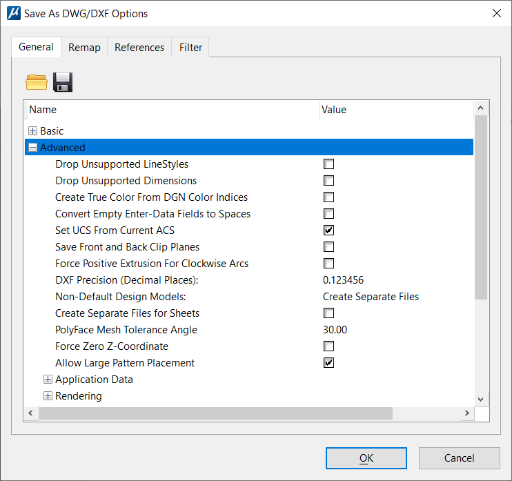
Save As DWG/DXF Options Dialog, General Tab, Advanced
Used to set advanced options for saving to DWG and DXF files. Opens when you select , select AutoCAD Drawing Files (*.dwg) from the Save as Type list, and click the Options button.
Other groups of options under the General tab include:
| Setting | Description |
|---|---|
| Drop Unsupported LineStyles | If on, drops elements that use custom line styles not supported by AutoCAD to individual components. |
| Drop Unsupported Dimensions | If on, drops dimensions which use features that are not supported by DWG. Some examples of dimension features not supported by DWG are DIN dimensions that are effectively superscripted, dimension text that is pushed outside the extension lines due to fit options, and radial dimension whose text is placed beyond the center point. Such dimensions are dropped to the geometry as shared cells in a DWG file. These shared cells will look the same as the original dimensions in the DGN file, but will no longer be dimensions. |
| Create True Color From DGN Color Indices | MicroStation supports arbitrary, custom color tables, whereas AutoCAD supports only a fixed table. When a color from a MicroStation table is saved to AutoCAD, it can use either the closest color in the AutoCAD table, or a "True Color". If this setting is checked on, and there is not an exact match in the AutoCAD table, a True Color (RGB) color is used. |
| Convert Empty Enter-Data Fields to Spaces | If on, converts empty enter data fields within text to space characters ("") when the DGN file is saved to DWG. If off, enter data fields are converted to underscore characters ("_"). |
| Set UCS from Current ACS | If on, sets the AutoCAD UCS (User Coordinate System) from the current ACS (Auxiliary Coordinate System) when the DGN file is saved to DWG. AutoCAD's UCS is similar to MicroStation's ACS, but the UCS is more heavily used in AutoCAD. In particular, AutoCAD always displays coordinate values in the current UCS. This can cause a mismatch with MicroStation, which by default displays world coordinates. |
| Save Front and Back Clip Planes | If on, sets the front and back clipping planes when a view in a DGN file is saved to DWG. If off, the clipping planes are not defined in the DWG file. In AutoCAD the clipping planes are not widely used and are difficult to control, so the recommended setting is Off. |
| Force Positive Extrusion For Clockwise Arcs | When on, maintains a positive extrusion (and
reverses arc direction) when saving clockwise arcs to DWG.
In AutoCAD, arc entities are drawn counterclockwise, while in MicroStation, arcs can be specified in either direction. When saving a clockwise arc to DWG, the direction can be maintained by reversing the extrusion vector. This maintains the arc direction, but the negated extrusion can make the arc difficult to enter within AutoCAD. |
| DXF Precision (Decimal Places) | Controls the number of decimal places that are
saved to DXF files.
The default is 6, but the value can be increased to as high as 16 to create more precise (but larger) DXF files. |
| Non-Default Design Models | Defines how non-default design models are saved to
DWG files. A DGN file can have multiple design models and sheet models. In
contrast, a DWG file can have only one design model and multiple sheet models.
When a DGN file is saved to DWG, the default design model is saved to model
space in the DWG file, and the sheet models are saved to drawing layouts (paper
space).
|
| Create Separate Files for Sheets | If on, a separate DWG file is created for each sheet model in the DGN file. |
| PolyFace Mesh Tolerance Angle | Controls the accuracy of the approximation when
elements are saved to polyface mesh entities (see
Entity Mapping
options).
If curved surfaces or complex shapes with curved boundaries are saved as polyface meshes, then the curved geometry is approximated by the polygonal faces of the mesh. A small angle creates a more accurate representation, but it also increases file size and mesh complexity. |
| Force Zero Z-Coordinate | If on, the resultant DWG entities will have
z-coordinates of zero value. This should only be used for 3D DGN files that
represent a 2D drawing but some geometry may contain none-zero values in their
z-coordinate. In addition to zero z-coordinate, group hole cells will get
dropped to block references and planar mesh elements get dropped to visible
edge entities (usually boundary edges).
If the configuration variable MS_DWG_FORCE_ZERO_ZCOORDINATE is present then the toggle is set to the ON state. |
| Allow Large Pattern Placement | If on, allows large valid patterns (> MAX_PATTERN_LIMIT = 1.0E7) to be saved to the DWG files. |
| Application Data | Controls whether non-displayable application data is saved to the DWG file. These settings also control whether application data created while editing a DWG file is saved back to the DWG file. MicroStation application data can be attached to individual elements as attribute linkages, or it can be stored as separate Type 66, Level 20 elements. Within a DWG file, data can be attached to entities as extended data (XData) or extended records (XRecords). |
| Application Data > Save Application Data | If on, saves element attribute linkages to DWG
XData, and saves application elements (Type 66, Level 20) to XRecords. When the
DWG file is opened in
MicroStation, this non-displayable
application data is automatically restored to the file. In other words, XData
is converted back to the original linkages, and application elements are
created from the XRecords.
Since the application data is generally not required or useful in the DWG file, this option is off by default. |
| Rendering | Controls how materials and light sources are saved when converting to DWG. |
| Rendering > Materials | If on, the materials in a DGN file are saved to the DWG file. The default is On. |
| Rendering > Light Sources | If on, the light sources in a DGN file are saved to the DWG file. The default is On. |