| Open DWG Settings File (icon)
|
Opens the Open DWG Settings File dialog, which lets
you select and load a DWG settings file (*.dws). The DWG settings file contains
settings for opening and saving DWG files.
The default directory for the settings file is the
DWG settings directory as specified by the configuration variable
MS_DWGDATA.
DWG
SETTINGS
OPEN
[
filename
]
|
| Save DWG Settings File (icon)
|
Opens the Save DWG Settings File dialog, which lets
you save the DWG Open and Save As options to a DWG settings file (*.dws).
The default directory for the settings file is the
DWG settings directory as specified by the configuration variable
MS_DWGDATA.
DWG
SETTINGS
SAVEAS
[
FILENAME
]
|
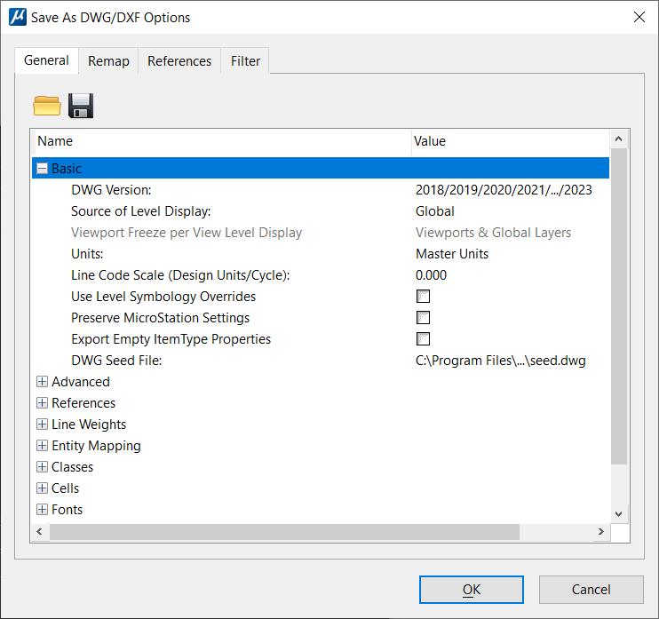
| DWG Version
|
Sets the AutoCAD release version that corresponds
to the version of DWG file that will be saved. Each version of AutoCAD reads
and writes DWG files only from that version or a prior version.
MicroStation can save DWG files for
versions AutoCAD v14 and higher, and DXF files for versions 11/12 and higher.
Usually you should save files in the most recent version because older versions
may not support all data constructs necessary for optimum conversion. Versions
include:
- 11/12 (DXF only)
- 14
- 2000/2000i/2002
- 2004/2005/2006
- 2007/2008/2009
- 2010/2011/2012
-
2013/2014/2015/2016/2017
- 2018/2019/2020/2021/2022/2023
|
| Source of Level Display
|
Controls how levels are displayed in the DWG file.
If set to Global, the AutoCAD layers visibility is
controlled from the global setting, and the levels that are turned off on a
per-view basis are turned on in the AutoCAD file.
If set to one of the eight views, the AutoCAD
layers are not visible if they are turned off either globally or in that view.
Although
MicroStation allows you to turn on
and turn off levels either globally or on a per-view basis, AutoCAD allows only
global control.
|
| Viewport Freeze per View Level Display
|
(Active only when
"Source of Level Display" setting has a view
selected) Sets how a sheet model is saved to DWG with the desired level display
state. When the default design model is attached to a sheet model, it is saved
as a viewport in DWG. While DWG does not support per view based level display,
in addition to globally frozen layers such viewport can have a list of frozen
layers. When a source view is selected for DWG save, the view level display may
be applied to Viewport Freeze, with following options:
- Viewports &
Global Layers
Applies overall source view's level display to
output DWG layers, including global display and global frozen levels. Following
is the impact of the setting on different DWG features:
- Global layers -
level state may change as a result of applying view level display.
Specifically, levels that are turned off in the selected source view are
globally turned off when saved to DWG. In effect, levels globally turned off
stay as globally turned off, and levels globally turned on may also be globally
turned off.
- Viewport
entities - levels that are turned off per selected source view are frozen in
the output viewport.
- Layout viewports
- no frozen levels are added to layout viewports. Layout viewport display is
completely controlled by global level state.
- xRef attachments
- because levels of an xRef are essentially global levels, they are generally
controlled by global level display state. However, if an xRef is nested in a
viewport, its levels can also be controlled via viewport freeze.
This option allows the design model as well as
external reference attachments to have correct level display when saved to DWG.
However, sheet models with mixed level display will result in incorrect
display, generally more levels than desired get turned off. For example, if
"Level 1" is globally turned on, but is turned off in source View 1 in the
active sheet model, "Level 1" will be globally turned off after a DGN file is
saved as DWG. On the other hand, if "Level 1" is globally turned off, but is
turned on in the sheet model view, it will remain turned off in DWG.
- Viewport Only
Applies source view level display to viewport
freeze only. Following is the impact of the setting on different DWG features:
- Global layers -
view level display does not change global level state. Global level state
remains the same after DGN file is saved as DWG.
- Viewport
entities - levels that are turned off per selected source view are frozen in
the output viewport.
- Layout viewports
- levels that are turned off in a sheet model per view level display become
frozen layers in a layout viewport.
- xRef attachments
- level display is generally controlled via global level display state.
However, if an xRef is nested in a viewport, its levels can also be controlled
via viewport freeze.
For sheet model display, this option outputs
better result than Viewports & Global Layers. However, external reference
attachments may not display correctly, as view level display has no impact on
these levels.
- Force Global Layer
Display
This option applies source view level display
to viewport freeze. Additionally, it also globally thaws all the levels.
Following is the impact of the setting on different DWG features:
- Global layers -
all levels are unconditionally turned on.
- Viewport
entities - levels that are turned off in the selected source view are frozen in
the output viewport.
- Layout viewports
- levels that are turned off in a sheet model per view level display become
frozen layers in the layout viewport.
- xRef attachments
- global display state of all levels is unconditionally turned on. However,
those nested in a viewport may be turned off via viewport freeze.
This option provides a WYSIWYG level display
for a sheet model. However, the fact that levels globally turned off get
globally turned on may not be desirable for other cases. In particular, when
level display of the default model is required, this may not be the right
choice. For the same reason, external reference attachment will not display
correctly.
|
| Units
|
Sets the linear units of measurement used in the
AutoCAD file. Although
MicroStation allows you to select a
different unit system at any time without changing the actual size of the model
geometry, AutoCAD does not provide a convenient method for altering units.
Therefore, it is important that you select the correct output units. If you
select Master Units or Sub Units,
MicroStation uses the Master or Sub
units from the default model of the current file. Otherwise, you can select a
specific unit system. The Arch./Engineering (Feet/Inches) setting uses the
readout setting to determine whether the file is saved as
"Architectural" or
"Engineering".
- Master Units
- Sub Units
- Inches
- Feet
- Miles
- Millimeters
- Centimeters
- Meters
- Kilometers
- Microinches
- Mils
- Yards
- Arch./Engineering
(Feet/Inches) — Specifies that the file be saved with either
"Architectural" or
"Engineering" units, based on whether
fraction or decimal readout is used. When this option is selected, the file
will be saved with these units even if the current units do not match this
criteria.
|
| Line Code Scale (Design Units/Cycle)
|
Sets the scale value for
MicroStation line codes.
MicroStation's line codes (standard
line styles 1–7) are defined in screen units and are independent of the view
zoom factor. AutoCAD linetype definitions are always defined in drawing units
and are therefore not compatible with the
MicroStation line codes.
If Line Code Scale is set to the default value of
0.0, the lines will be scaled based on the size of the line codes in the first
visible view. If the Line Code Scale is set to a non-zero value, this value
represents the length (in DWG file units) of a single cycle of the line code
pattern.
|
| Use Level Symbology Overrides
|
If on, saves the DGN file level symbology to the
DWG file. The AutoCAD layers use the override colors and the DWG entity
properties are By Level. The resulting DWG file appears exactly as the DGN file
appears when it uses level symbology overrides.
|
| Preserve
MicroStation Settings
|
If on, preserves
MicroStation-specific settings in
the DWG file.
Many
MicroStation settings do not exist
in AutoCAD, and therefore cannot be saved as settings in the DWG file. These
settings include the active angle, active scale, and default tool settings.
Some elements may also have
MicroStation-specific data, such as
a graphic group number, that does not exist in the DWG format.
Use this setting if the DWG output file will be
edited with
MicroStation, and you want to
preserve the settings and element data between editing sessions.
MicroStation-specific settings are
saved to an XRECORD entity, and
MicroStation-specific element data
is saved as XDATA on each entity.
If the output file will not be edited with
MicroStation, then this data is not
required, and is ignored by other applications.
|
| Export Empty ItemType Properties
|
If ON exports the empty ItemType properties to the DWG or DXF
files. The default is OFF.
Note: Define the Configuration Variable
MS_DWG_EXPORT_EMPTYITEMTYPEPROPERTIES = 1 to
keep this setting ON by default.
Note: This functionality is available only for Graphic cells and
Shared cells.
|
| DWG Seed File
|
Sets the path and the file name of the seed DWG file
from which settings not present in the DGN file are extracted. To select
another file to be used as the DWG Seed file, click on the current file name to
open the Browse DWG Seed/Prototype File dialog.
|